


209
Communication operation and setting
4
PARAMETERS
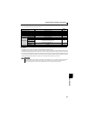
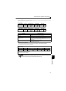
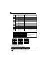
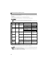
(6) Modbus registers
System environment variable
∗1 The communication parameter values are not cleared.
∗2 For write, set the data as a control input instruction.
For read, data is read as an inverter operating status.
∗3 For write, set data as the operation mode setting.
For read, data is read as the operation mode status.
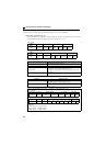
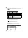
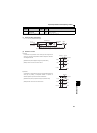
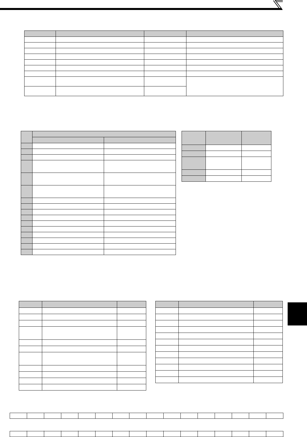
Real time monitor
Refer to page 128 for details of the monitor description.
∗1 When Pr.37 = "0.01 to 9998", displayed in integral number.
∗2 Input terminal monitor details
∗3 Output terminal monitor details
Register Definition Read/write Remarks
40002 Inverter reset Write Any value can be written
40003 Parameter clear Write Set H965A as a written value.
40004 All parameter clear Write Set H99AA as a written value.
40006 Parameter clear ∗1 Write Set H5A96 as a written value.
40007 All parameter clear ∗1 Write Set HAA99 as a written value.
40009 Inverter status/control input instruction∗2 Read/write See below.
40010 Operation mode/inverter setting ∗3 Read/write See below.
40014 Running frequency (RAM value) Read/write
According to the Pr. 37 settings, the frequency
and selectable speed are in 1r/min
increments.
40015 Running frequency (EEPROM value) Write
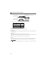
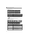
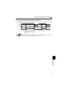
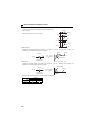
b15 b0
—————————RHRMRL——STRSTF
b15 b0
——————————ABC————RUN
<Inverter status/control input instruction>
∗1 The signal within parentheses is the initial setting. Definitions change according to the Pr. 180 to Pr. 182 (input terminal function selection) (refer to
page 113).
Each assigned signal is valid or invalid depending on NET. (Refer to page 176)
∗2
The signal within parentheses is the initial setting. Definitions change according to the
Pr. 190, Pr. 192 (output terminal function selection) (refer to page119)
.
Bit
Definition
Control input instruction Inverter status
0 Stop command RUN (inverter running) ∗2
1 Forward rotation command Forward rotation
2 Reverse rotation command During reverse rotation
3
RH (high-speed operation
command)∗1
SU (up-to-frequency)
4
RM (middle-speed operation
command)∗1
OL (overload)
5
RL (low-speed operation
command)∗1
0
6 0 FU (frequency detection)
7 RT (second function selection) ABC (fault) ∗2
8 AU (terminal 4 input selection) 0
90 0
10 MRS (output stop) 0
11 0 0
12 0 0
13 0 0
14 0 0
15 0 Fault occurrence
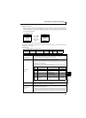
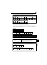
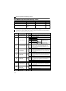
<Operation mode/inverter setting>
The restrictions depending on the operation
mode changes according to the computer
link specifications.
Mode Read Value
Written
Value
EXT H0000 H0010
PU H0001 —
EXT
JOG
H0002 —
NET H0004 H0014
PU+EXT H0005 —
Register
Description Unit
40201 Output frequency/speed 0.01Hz/1 ∗1
40202 Output current 0.01A
40203 Output voltage 0.1V
40205
Output frequency setting/speed
setting
0.01Hz/1 ∗1
40208 Converter output voltage 0.1V
40209 Regenerative brake duty 0.1%
40210
Electronic thermal relay function
load factor
0.1%
40211 Output current peak value 0.01A
40212 Converter output voltage peak value 0.1V
40214 Output power 0.01kW
40215 Input terminal status ∗2 —
40216 Output terminal status ∗3 —
40220 Cumulative energization time 1h
40223 Actual operation time 1h
40224 Motor load factor 0.1%
40225 Cumulative power 1kWh
40252 PID set point 0.1%
40253 PID measured value 0.1%
40254 PID deviation 0.1%
40261 Motor thermal load factor 0.1%
40262 Inverter thermal load factor 0.1%
40263 Cumulative power 2 0.01kWh
40264 PTC thermistor resistance 0.01kΩ
Register
Description Unit