


225
Special operation and frequency control
4
PARAMETERS
(9) Adjustment procedure
Dancer roller position detection signal adjustment
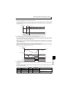
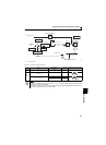
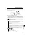
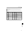
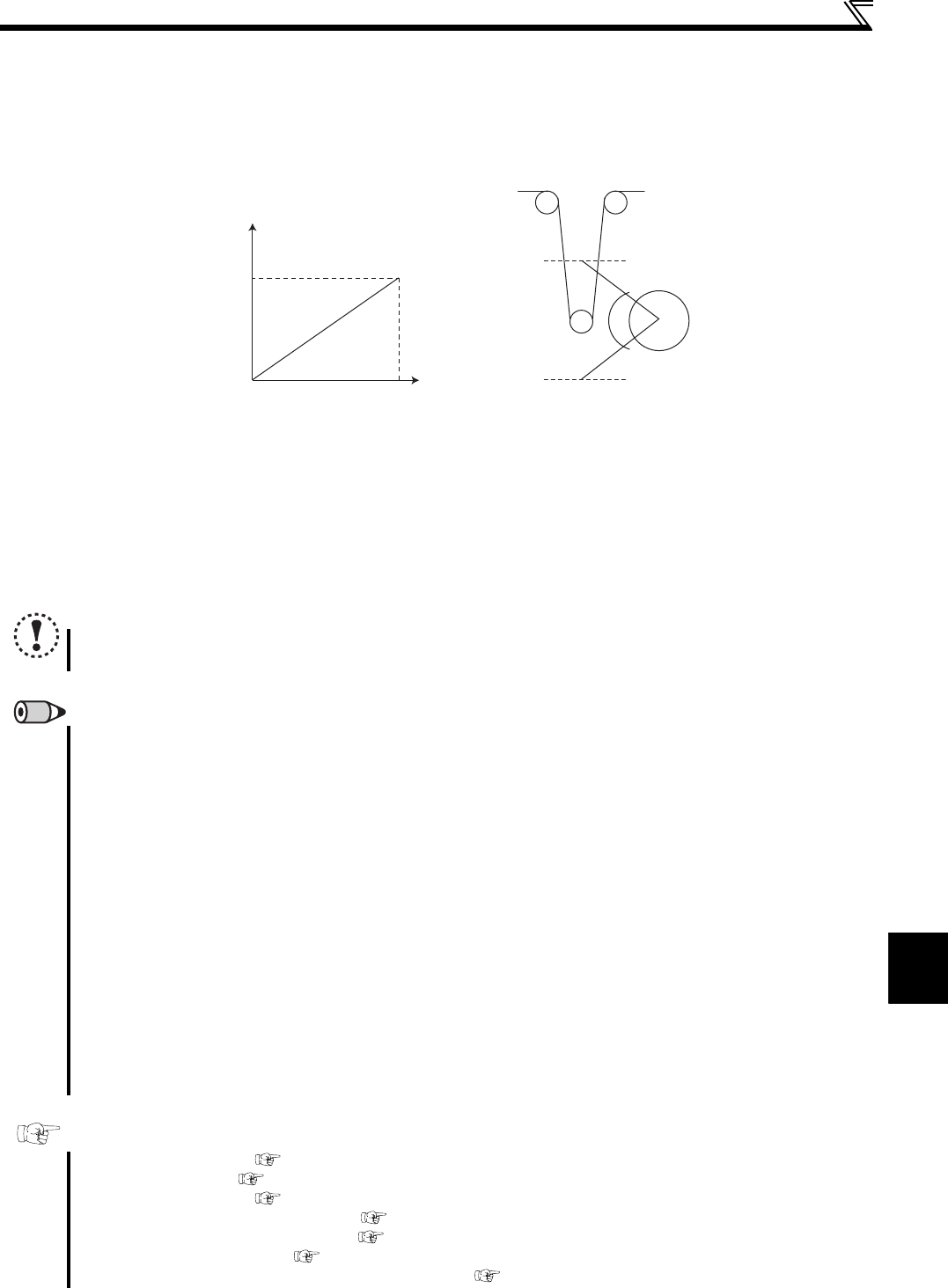
When terminal 4 input is voltage input, 0V is the minimum position and 5V(10V) is the maximum position. When current is
input, 4mA is the minimum position and 20mA is the maximum position. (initial value) When 0 to 7V is output from the
potentiometer, it is necessary to calibrate C7 (Pr .905) at 7V.
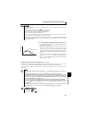
(Example) Control at a dancer center position using a 0 to 7V potentiometer
1) After changing the current/voltage input switch to "V", set "2" in Pr. 267 to change terminal 4 input to voltage input.
2) Input 0V to across terminal 4 and 5 to calibrate C6 (Pr. 904). (% display displayed at analog calibration is independent
to % of the feed back value.)
3) By inputting 7V to across terminal 4 to 5, calibrate C7(Pr. 905) (% display displayed at analog calibration is
independent to % of the feed back value.)
4) Set 50% in Pr.133.
NOTE
When the Pr. 267 setting was changed, check the voltage/current input switch setting. Different setting may cause a
fault, failure or malfunction. (Refer to page 150 for setting)
REMARKS
In normal PID control, PID control is stopped when multi-speed operation signal (RH, RM, RL, REX signal) or JOG signal is
input. In dancer control, however, PID control continues handling the signals as the main speed.
During dancer control, Second acceleration/deceleration time of Pr.44 and Pr.45 are the parameters for acceleration/deceleration
time setting to the main speed command source. They do not function as the second function.
When switchover mode is set with "6" in Pr. 79, dancer control (PID control) is invalid.
Speed command of terminal 4 input from terminal AU is invalid when dancer control is selected.
Acceleration/deceleration of the main speed command is the same operation as when frequency command is increased/
decreased by analog input.
Therefore, SU signal remains ON even if the starting signal is turned ON/OFF.(always in the constant speed state)
The DC brake operation starting frequency when turning off the starting signal is not Pr. 10 but a smaller value of either Pr. 13
or 0.5Hz.
The set frequency monitor is always variable as "main speed command+PID control".
The main speed setting frequency accelerates for the acceleration/deceleration time set in Pr. 44 and Pr. 45 and the output
frequency accelerates/decelerates for the acceleration/deceleration time set in Pr. 7 and Pr. 8. Therefore, when the set time of
Pr. 7 and Pr. 8 is longer than Pr. 44 and Pr. 45, the output frequency accelerates/decelerates for the acceleration/deceleration
time set in Pr. 7 and Pr. 8.
For the integral term limit, a smaller value of either the PID manipulated variable (%) value converted from the linear
interpolated Pr. 1 Maximum frequency with Pr. 902 and Pr. 903 , or 100% is used for limit.
Although the output frequency is limited by the minimum frequency, operation limit of the integral term is not performed.
Parameters referred to
Pr. 59 Remote function selection Refer to page 93
Pr. 73 Analog input selection Refer to page 150
Pr. 79 Operation mode selection Refer to page 165
Pr. 178 to Pr. 182 (input terminal function selection) Refer to page 113
Pr. 190, Pr. 192 (output terminal function selection) Refer to page 119
Pr. 561 PTC thermistor protection level Refer to page 100
C2 (Pr. 902) to C7 (Pr. 905) Frequency setting voltage (current) bias/gain Refer to page 153
5V(10V)
0V
20mA
4mA
0%
Feedback value
Potentiometer, etc.
Lower limit
position
Upper limit
position
100%