


20
Control circuit specifications
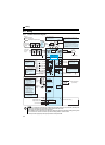
2.3 Control circuit specifications
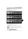
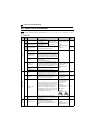
2.3.1 Control circuit terminal
indicates that terminal functions can be selected using Pr. 178 to Pr. 182, Pr. 190, Pr. 192 (I/O terminal function selection).
(Refer to page 113).
(1) Input signal
Type
Terminal
Symbol
Terminal Name Description Rated Specifications
Refer to
Page
Contact input
STF Forward rotation start
Turn on the STF signal to
start forward rotation and
turn it off to stop.
When the STF and STR
signals are turned on
simultaneously, the stop
command is given.
Input resistance 4.7kΩ
Voltage when contacts are
open
21 to 26VDC
When contacts are short-
circuited
4 to 6mADC
117
STR Reverse rotation start
Turn on the STR signal to
start reverse rotation and
turn it off to stop.
RH,
RM,
RL
Multi-speed selection
Multi-speed can be selected according to the
combination of RH, RM and RL signals.
89
SD
Contact input common
(sink) (initial setting)
Common terminal for contact input terminal (sink
logic).
——
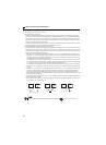
External transistor
common (source)
When connecting the transistor output (open collector
output), such as a programmable controller, when
source logic is selected, connect the external power
supply common for transistor output to this terminal to
prevent a malfunction caused by undesirable currents.
24VDC power supply
common
Common output terminal for 24VDC 0.1A power
supply (PC terminal).
Isolated from terminals 5 and SE.
PC
External transistor
common (sink)
(initial setting)
When connecting the transistor output (open collector
output), such as a programmable controller, when sink
logic is selected, connect the external power supply
common for transistor output to this terminal to prevent
a malfunction caused by undesirable currents.
Power supply voltage range
22 to 26.5VDC
permissible load current
100mA
23
Contact input common
(source)
Common terminal for contact input terminal (source
logic).
24VDC power supply Can be used as 24VDC 0.1A power supply.
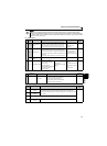
Frequency setting
10
Frequency setting power
supply
Used as power supply when connecting potentiometer
for frequency setting (speed setting) from outside of
the inverter. (Refer to Pr. 73 Analog input selection.)
5.0V ± 0.2VDC
permissible load current
10mA
150
2
Frequency setting
(voltage)
Inputting 0 to 5VDC (or 0 to 10V) provides the maximum
output frequency at 5V (10V) and makes input and output
proportional. Use
Pr. 73
to switch between input 0 to
5VDC input (initial setting) and 0 to 10VDC.
Input resistance10kΩ ± 1kΩ
Permissible maximum
voltage 20VDC
150
4
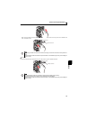
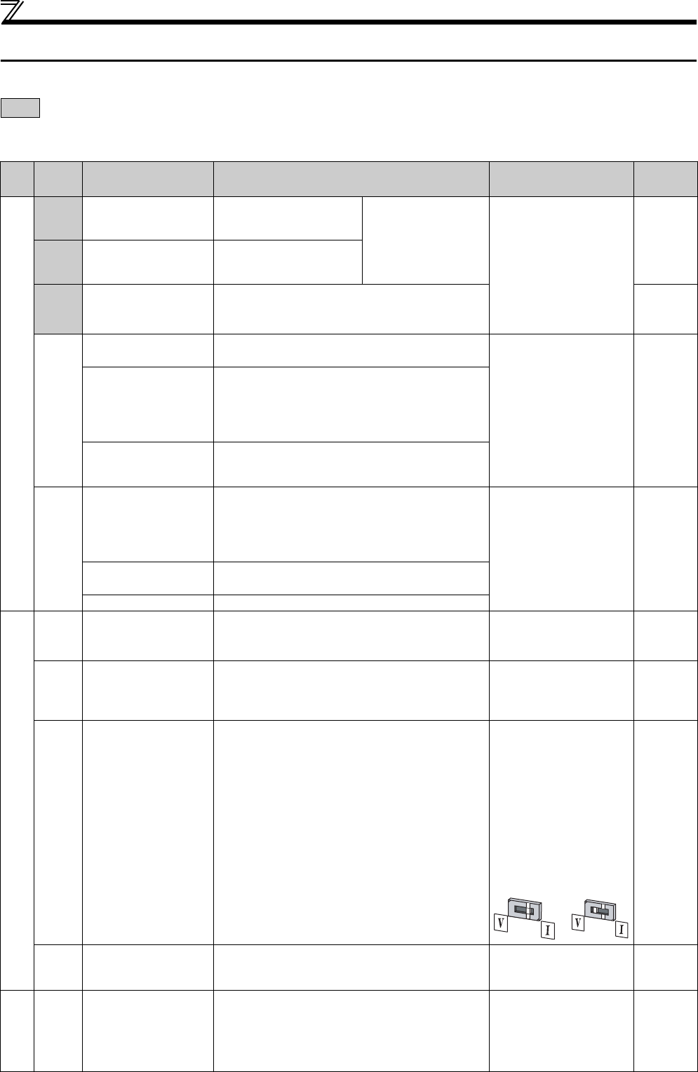
Frequency setting
(current)
Inputting 4 to 20mADC (or 0 to 5V, 0 to 10V) provides
the maximum output frequency at 20mA and makes
input and output proportional. This input signal is valid
only when the AU signal is on (terminal 2 input is
invalid). Use Pr. 267 to switch from among input 4 to
20mA (initial setting), 0 to 5VDC and 0 to 10VDC. Set
the voltage/current input switch in the "V" position to
select voltage input (0 to 5V/0 to 10V).
Current input:
Input resistance 233Ω ± 5Ω
Maximum permissible
current 30mA
Voltage input:
Input resistance10kΩ ± 1kΩ
Permissible maximum
voltage 20VDC
150
5
Frequency setting
common
Common terminal for frequency setting signal
(terminal 2 or 4) and analog output terminal AM. Do
not earth (ground).
——
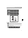
PTC thermistor
10
2
PTC thermistor input
For connecting PTC thermistor output.
When PTC thermistor protection is valid (Pr. 561 ≠
"9999"), terminal 2 is not available for frequency
setting.
Adaptive PTC thermistor
specification
Heat detection resistance :
500
Ω
to 30k
Ω
(Set by
Pr. 561
)
100
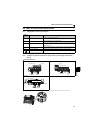
Voltage input
Current input
(initial status)