


257
5
TROUBLESHOOTING
Causes and corrective actions
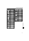
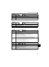
Operation panel
indication
E.OHT
FR-PU04
FR-PU07
OH Fault
Name
External thermal relay operation
Description
If the external thermal relay provided for motor overheat protection or the internally mounted temperature relay in the
motor, etc. switches on (contacts open), the inverter output is stopped.
Functions when "7" (OH signal) is set in any of Pr. 178 to Pr. 182 (input terminal function selection).
This protective function does not function in the initial status (OH signal is not assigned).
Check point
Check for motor overheating.
Check that the value of 7 (OH signal) is set correctly in any of Pr. 178 to Pr. 182 (input terminal function selection).
Corrective action
Reduce the load and frequency of operation.
Even if the relay contacts are reset automatically, the inverter will not restart unless it is reset.
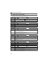
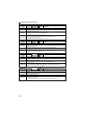
Operation panel
indication
E.PTC
FR-PU04 Fault 14
FR-PU07 PTC activated
Name
PTC thermistor operation
Description
Inverter trips when resistance of PTC thermistor connected between terminal 2 and terminal 10 is more than the
value set in Pr. 561 PTC thermistor protection level. This protective function does not function when Pr. 561 setting is
initial value (Pr. 561 = "9999").
Check point
Check the connection of the PTC thermistor.
Check the Pr. 561 PTC thermistor protection level setting.
Check the motor for operation under overload.
Corrective action
Reduce the load weight.
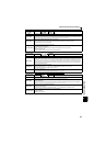
Operation panel
indication
E.PE
FR-PU04
FR-PU07
Corrupt Memry
Name
Parameter storage device fault (control circuit board)
Description
Appears when a fault occurred in the stored parameters. (EEPROM fault)
Check point
Check for too many number of parameter write times.
Corrective action
Please contact your sales representative.
When performing parameter write frequently for communication purposes, set "1" in Pr. 342 to enable RAM write. Note
that powering off returns the inverter to the status before RAM write.
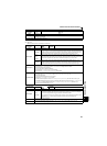
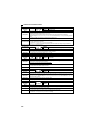
Operation panel
indication
E.PUE
FR-PU04
FR-PU07
PU Leave Out
Name
PU disconnection
Description
This function stops the inverter output if communication between the inverter and PU is suspended, e.g. the
parameter unit (FR-PU04/FR-PU07) is disconnected, when "2", "3", "16" or "17" was set in Pr. 75 Reset selection/
disconnected PU detection/PU stop selection.
This function stops the inverter output when communication errors occurred consecutively for more than permissible
number of retries when a value other than "9999" is set in Pr. 121 Number of PU communication retries during the RS-
485 communication with the PU connector (use Pr. 502 Stop mode selection at communication error to change).
This function also stops the inverter output if communication is broken within the period of time set in Pr. 122 PU
communication check time interval during the RS-485 communication with the PU connector.
Check point
Check that the parameter unit cable is fitted tightly.
Check the Pr. 75 setting.
Check that RS-485 communication data is correct. And check that the settings of communication parameter at
inverter match settings of the computer.
Check that data is transmitted from the computer within a time set in Pr. 122 PU communication check time interval.
Corrective action
Connect the parameter unit cable securely.
Check the communication data and communication settings.
Increase the Pr. 122 PU communication check time interval setting. Or set "9999" (no communication check).
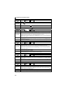
Operation panel
indication
E.RET
FR-PU04
FR-PU07
Retry No Over
Name
Retry count excess
Description
If operation cannot be resumed properly within the number of retries set, this function trips the inverter.
Functions only when Pr. 67 Number of retries at fault occurrence is set.
When the initial value (Pr. 67 = "0") is set, this protective function does not function.
Check point
Find the cause of fault occurrence.
Corrective action
Eliminate the cause of the error preceding this error indication.