


155
Frequency setting by analog input (terminal 2, 4)
4
PARAMETERS
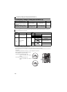
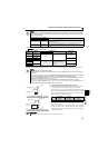
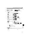
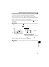
(4) Frequency setting signal (current) bias/gain adjustment method
(a) Method to adjust any point by application of a voltage (current) across terminals 2-5 (4-5).
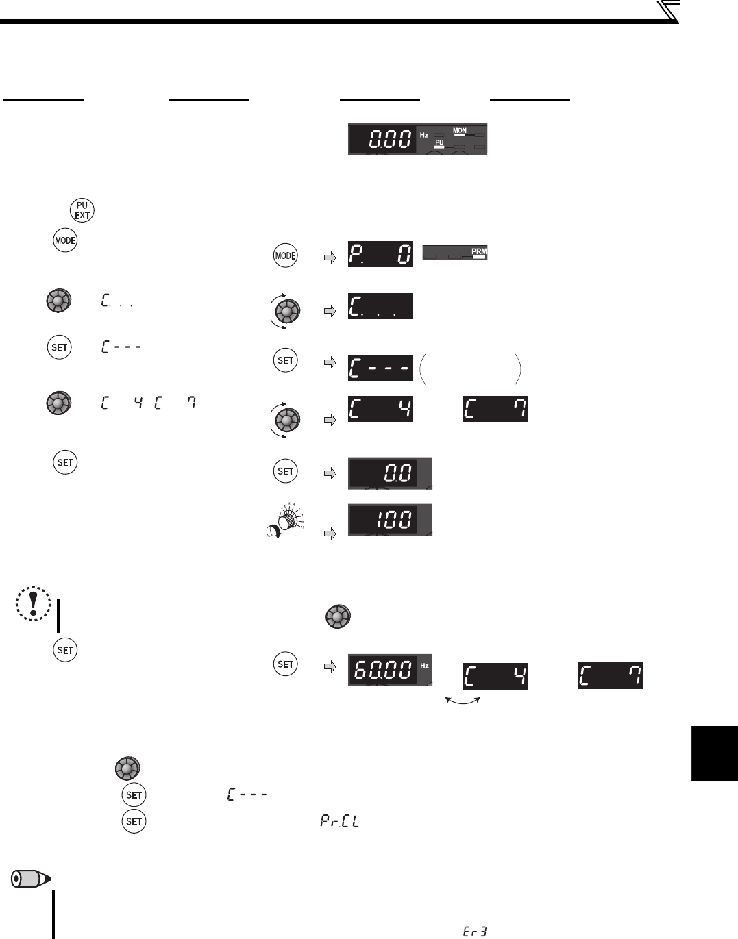
Operation Display
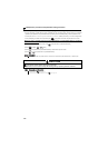
1.
Confirm the RUN indication and operation
mode indication
The inverter should be at a stop.
The inverter should be in the PU operation
mode.
(Using )
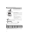
2. Press to choose the parameter setting
mode.
PRM indication is lit.
(The parameter number read previously appears.)
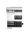
3. Turn until appears.
4. Turn until appears.
5. Turn until ( ) appears.
Set to C4 Terminal 2 frequency setting gain.
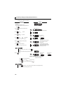
Terminal 2 input is
selected
Terminal 4 input is
selected
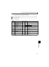
6. Press to display the analog voltage
(current) value (%).
Analog voltage (current)
value (%) across terminals 2-
5 (across terminals 4-5)
7. Apply a 5V (20mA) voltage (current).
(Turn the external potentiometer connected
across terminals 2-5 (across terminals 4-5) to
maximum (any position).)
∗
* The value is nearly 100 (%) in the maximum position of
the potentiometer.
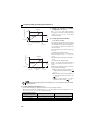
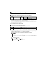
8. Press to set.
Terminal 2 input is
selected
Terminal 4 input is
selected
Flicker...Parameter setting complete!!
* The value is nearly 100 (%) in the maximum position of
the potentiometer.
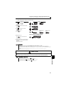
Turn to read another parameter.
Press to return to the indication (step 4).
Press twice to show the next parameter ( ).
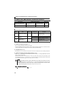
REMARKS
If the frequency meter (display meter) connected across the terminals AM-5 does not indicate exactly 60Hz, set the calibration
parameter C1 AM terminal calibration. (Refer to page 134)
If the gain and bias of frequency setting voltage (current) are too close, an error ( ) may be displayed at setting.
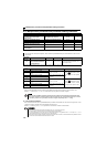
C1 to C7 settings
are enabled.
NOTE
After performing operation in step 6, do not touch until completion of calibration.
∗