


233
Useful functions
4
PARAMETERS
4.21.3 Maintenance timer alarm (Pr. 503, Pr. 504)
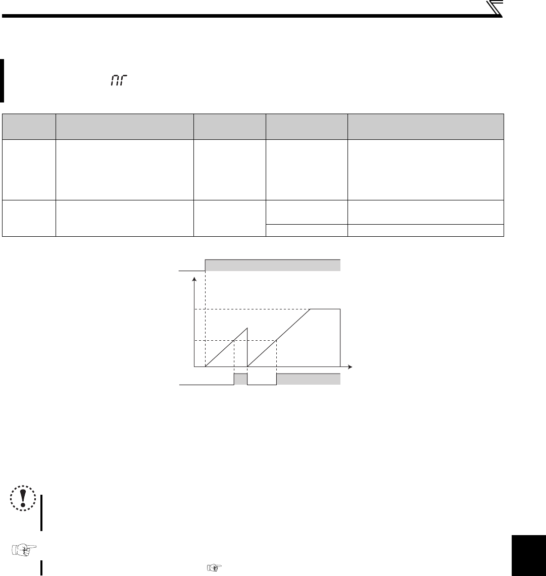
The cumulative energization time of the inverter is stored into the EEPROM every hour and is displayed in Pr. 503
Maintenance timer in 100h increments. Pr. 503 is clamped at 9998 (999800h).
When the Pr. 503 value reaches the time set to Pr. 504 Maintenance timer alarm output set time (100h increments), the
maintenance timer alarm output signal (Y95) is output.
For the termial used for the Y95 signal output, assign the function by setting "95" (positive logic) or "195" (negative logic) to
Pr. 190 or Pr. 192 (output terminal function selection).
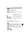
When the cumulative energization time of the inverter reaches the parameter set time, the maintenance timer output
signal (Y95) is output. (MT) is displayed on the operation panel.
This can be used as a guideline for the maintenance time of peripheral devices.
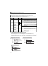
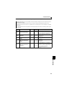
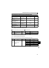
Parameter
Number
Name Initial Value Setting Range Description
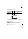
503 Maintenance timer
0 0 (1 to 9998)
Displays the cumulative energization time
of the inverter in 100h increments.
(Reading only)
Writing the setting of "0" clears the
cumulative energization time.
504
Maintenance timer alarm
output set time
9999
0 to 9998
Time taken until when the maintenance
timer alarm output signal (Y95) is output.
9999 No function
The above parameters can be set when Pr. 160 Extended function display selection = "0". (Refer to page 162)
NOTE
The cumulative energization time is counted every hour. The energization time of less than 1h is not counted.
Changing the terminal assignment using Pr. 190, Pr. 192 (output terminal function selection) may affect the other functions.
Make setting after confirming the function of each terminal.
Parameters referred to
Pr. 190, Pr. 192 (output terminal function selection) Refer to page 119
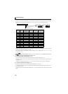
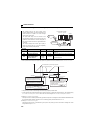
First power
Time
ON
Maintenance
timer
(Pr. 503)
Set "0" in Pr. 503
Y95 signal
MT display
OFF ONON
Pr. 504
9998
(999800h)