


221
Special operation and frequency control
4
PARAMETERS
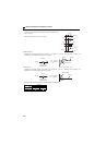
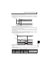
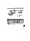
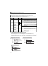
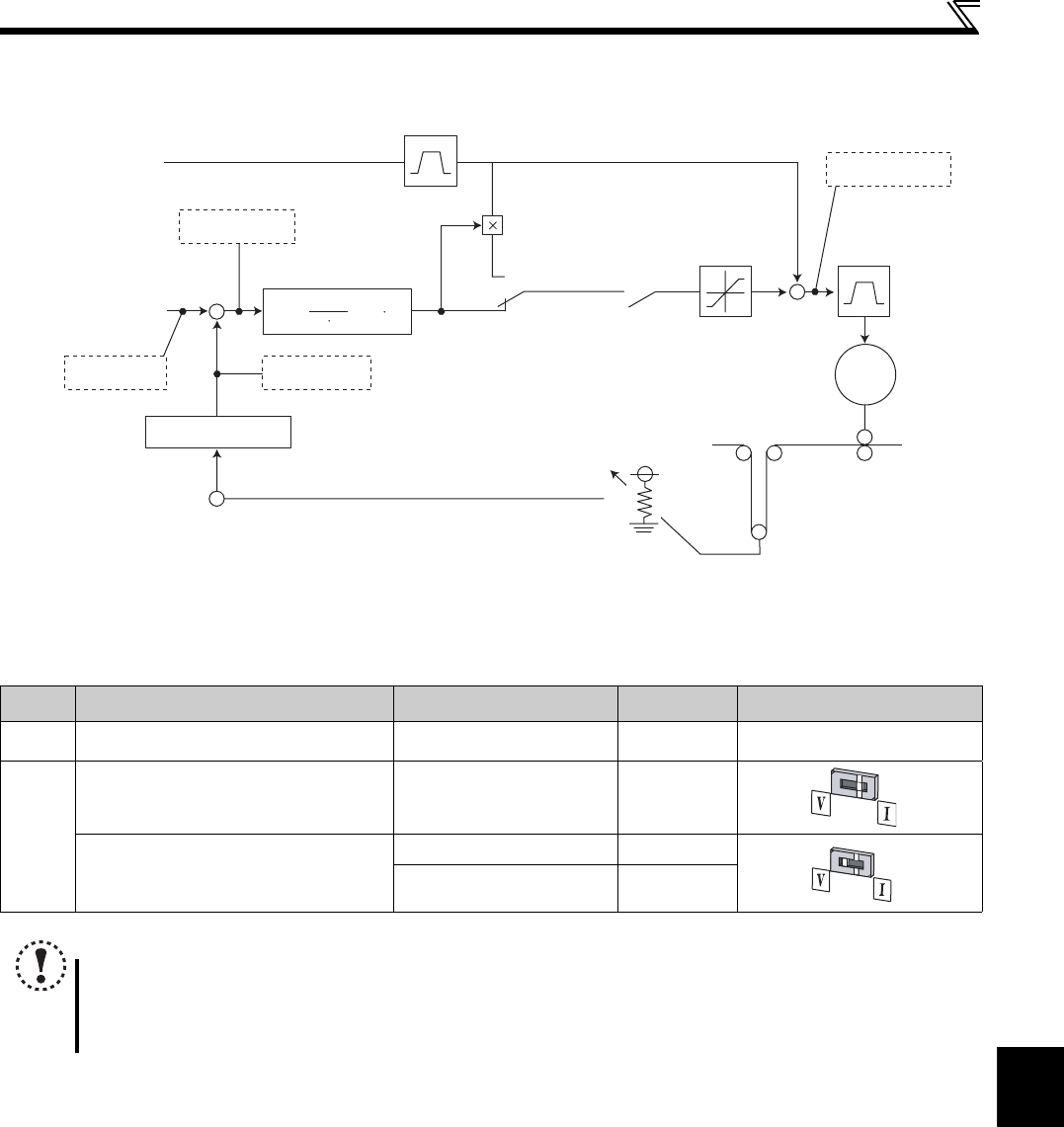
(1) Dancer control block diagram
∗1 The main speed can be selected from all operation mode such as external (analog voltage input, multi-speed), PU (digital frequency setting), and
communication (RS-485).
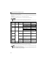
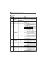
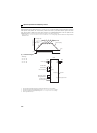
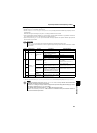
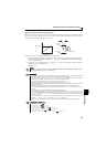
Set point and measured value of PID control
Input Input Signal Pr.267 Setting Voltage/Current Input Switch
Set point Pr. 133 0 to 100% — —
Measured
value
When measured value is input as current
(4 to 20mA)
4mA
..... 0%, 20mA ..100%
0
When measured value is input as voltage
(0 to 5V or 0 to 10V)
0V
........ 0%, 5V ........100%
1
0V.......... 0%, 10V....... 100%
2
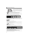
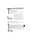
NOTE
Changing the terminal function using any of Pr.178 to Pr.182 may affect the other functions. Make setting after
confirming the function of each terminal.
When the Pr. 267 setting was changed, check the voltage/current input switch setting. Different setting may cause a
fault, failure or malfunction. (Refer to page 150 for setting)
Limit
Ratio
Acceleration/deceleration
of main speed
Main speed command
*1
Terminal 4
Potentiometer
Pr. 128 = 42, 43
Pr. 128 = 40, 41
Dancer roll position detection
PID control
PID deviation
PID feedback
PID set point
Target frequency
X14
Acceleration/
deceleration
+
+
-
+
Kp(1+
Convert to 0 to 100%
IM
Dancer roll
setting point
Pr. 133
Ti S
1
+
Td S)