


154
Frequency setting by analog input (terminal 2, 4)
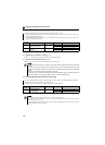
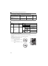
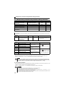
(3) Analog input display unit changing (Pr. 241)
You can change the analog input display unit (%/V/mA) for analog input bias/gain calibration.
Depending on the terminal input specification set to Pr. 73, Pr. 267, and voltage/current switch, the display units of C3 (Pr.
902), C4 (Pr. 903), C6 (Pr. 904), C7 (Pr. 905) change as shown below.
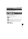
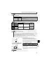
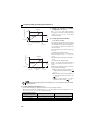
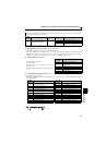
(1) Change the frequency at maximum
analog input (Pr. 125, Pr. 126)
Set Pr. 125 (Pr. 126) when changing frequency
setting (gain) of the maximum analog input voltage
(current) only. (C2 (Pr. 902) to C7 (Pr.905) setting
need not be changed)
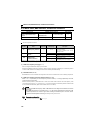
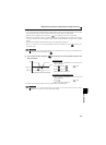
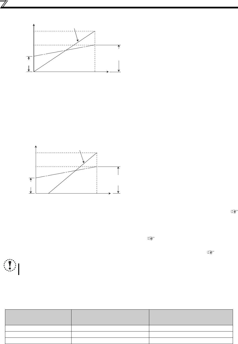
(2) Analog input bias/gain calibration
(C2 (Pr. 902) to C7 (Pr. 905))
The "bias" and "gain" functions are used to adjust
the relationship between the input signal entered
from outside the inverter to set the output frequency,
e.g. 0 to 5VDC, 0 to 10VDC or 4 to 20mADC, and
the output frequency.
Set the bias frequency of the terminal 2 input using
C2 (Pr. 902).
(It is initially set to the frequency at 0V)
Set the output frequency in Pr. 125 for the frequency
command voltage set with Pr. 73 Analog input
selection.
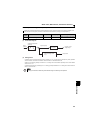
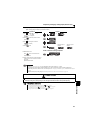
Set the bias frequency of the terminal 4 input using
C5
(Pr. 904).
(It is
initially
set to the frequency at 4mA)
Using Pr. 126, set the output frequency relative to
20mA of the frequency command current (4 to
20mA).
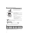
There are three methods to adjust the frequency
setting voltage (current) bias/gain.
a) Method to adjust any point by application of a
voltage (current) across terminals 2-5 (4-5)
page 155
b) Method to adjust any point without application of
a voltage (current) across terminals 2-5 (4-5)
page 156
c) Method to adjust frequency only without
adjustment of voltage (current) page 157
NOTE
When voltage/current input signal for terminal 4 was switched using Pr. 267 and voltage/current input switch, perform
calibration without fail.
Analog Command (terminal 2, 4)
(depending on Pr. 73, Pr. 267, and
voltage/current input switch)
Pr. 241 = 0 (initial value) Pr. 241 = 1
0 to 5V input 0 to 5V 0 to 100% (0.1%) display 0 to 100% 0 to 5V (0.01V) display
0 to 10V input 0 to 10V 0 to 100% (0.1%) display 0 to 100% 0 to 10V (0.01V) display
0 to 20mA input 0 to 20mA 0 to 100%(0.1%) display 0 to 100% 0 to 20mA (0.01mA) display
C2(Pr. 902)
C3(Pr. 902) C4(Pr. 903)
60Hz
Output frequency (Hz)
0
0
Frequency setting signal
100%
10V
Initial value
Bias
05V
Pr. 125
Gain
C5(Pr. 904)
C6(Pr. 904) C7(Pr. 905)
60Hz
Pr. 12
6
0
Frequency setting
signal
100%
Initial value
Bias
Gain
0
20
4 20mA
Output frequency (Hz)