


41
3
PRECAUTIONS FOR USE OF THE INVERTER
EMC and leakage currents
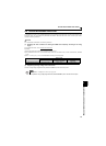
Data line filter
As immunity measures it may effective, provide a data line filter for the detector cable etc.
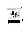
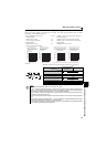
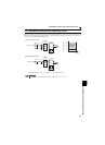
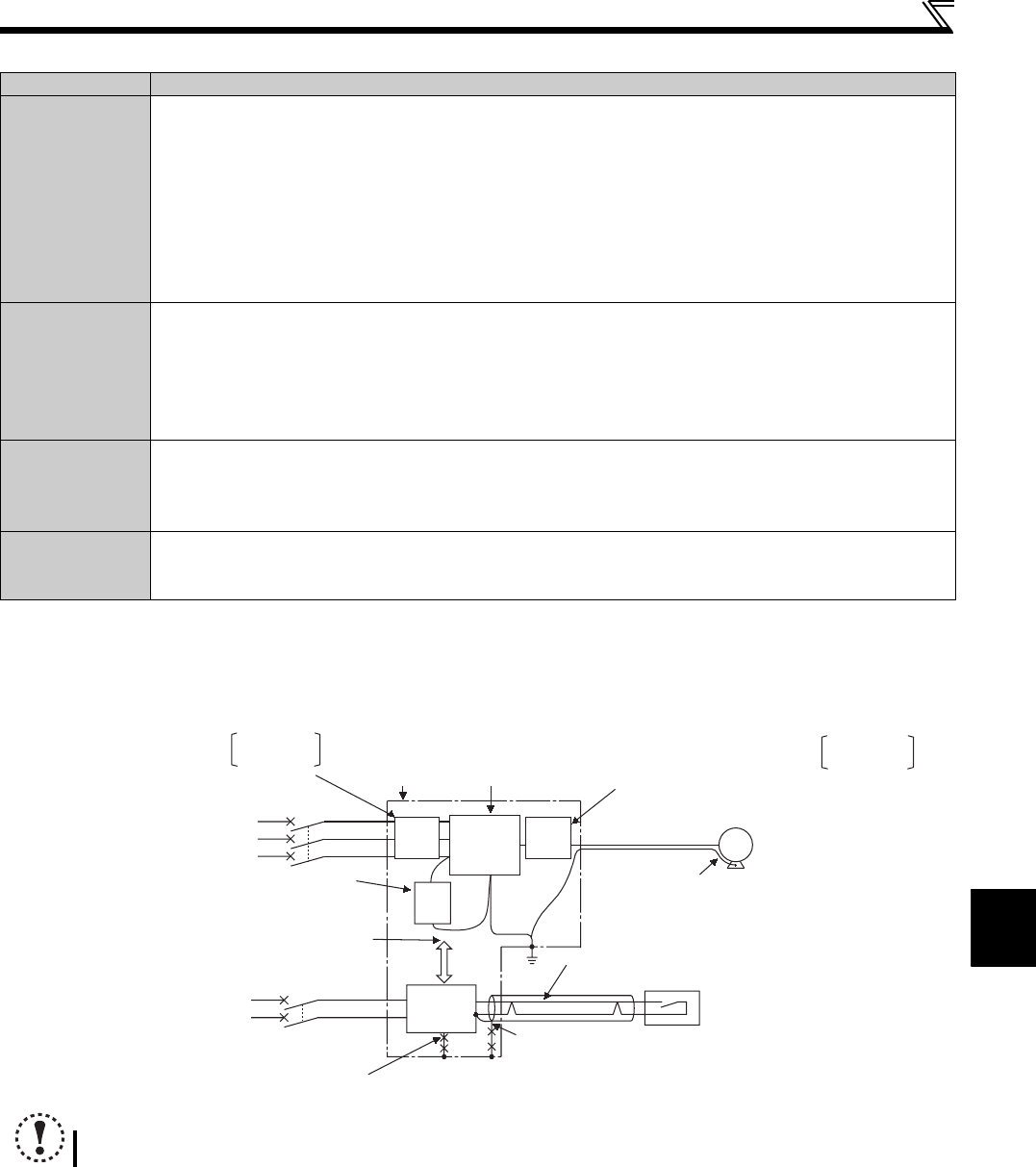
EMC measures
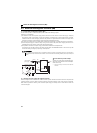
Propagation Path Measures
(1)(2)(3)
When devices that handle low-level signals and are liable to malfunction due to electromagnetic noises, e.g.
instruments, receivers and sensors, are contained in the enclosure that contains the inverter or when their signal
cables are run near the inverter, the devices may be malfunctioned by air-propagated electromagnetic noises. The
following measures must be taken:
Install easily affected devices as far away as possible from the inverter.
Run easily affected signal cables as far away as possible from the inverter and its I/O cables.
Do not run the signal cables and power cables (inverter I/O cables) in parallel with each other and do not bundle them.
Insert common mode filters into I/O and capacitors between the input lines to suppress cable-radiated noises.
Use shield cables as signal cables and power cables and run them in individual metal conduits to produce further effects.
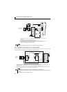
(4)(5)(6)
When the signal cables are run in parallel with or bundled with the power cables, magnetic and static induction noises
may be propagated to the signal cables to malfunction the devices and the following measures must be taken:
Install easily affected devices as far away as possible from the inverter.
Run easily affected signal cables as far away as possible from the I/O cables of the inverter.
Do not run the signal cables and power cables (inverter I/O cables) in parallel with each other and do not bundle them.
Use shield cables as signal cables and power cables and run them in individual metal conduits to produce further effects.
(7)
When the power supplies of the peripheral devices are connected to the power supply of the inverter in the same line,
inverter-generated noises may flow back through the power supply cables to malfunction the devices and the
following measures must be taken:
Install the common mode filter (FR-BLF, FR-BSF01) to the power cables (output cable) of the inverter.
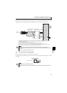
(8)
When a closed loop circuit is formed by connecting the peripheral device wiring to the inverter, leakage currents may
flow through the earth (ground) cable of the inverter to malfunction the device. In such a case, disconnection of the
earth (ground) cable of the device may cause the device to operate properly.
NOTE
For compliance with the EU EMC directive, refer to the Installation Guideline.
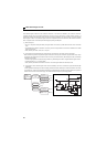
Inverter
Sensor
Use 4-core cable for motor
power cable and use one
cable as earth (ground) cable.
Use a twisted pair shielded cable
Inverter
power
supply
Control
power
supply
Do not earth (ground) shield but
connect it to signal common cable.
Enclosure
Decrease
carrier frequency
Motor
IM
FR-
BSF01
FR-
BSF01
FR-
BIF
Do not earth (ground)
enclosure directly.
Do not earth (ground) control cable.
Separate inverter and power line by
more than 30cm (11.81inches) (at least
10cm (3.93inches) from sensor circuit.
Install common mode filter
on inverter output side.
FR- BLF
FR- BSF01
Install capacitor type FR-BIF filter
on inverter input side.
Install common mode filter
on inverter input side.
FR- BLF
FR- BSF01
Power
supply
for sensor