


121
Function assignment of external terminal and control
4
PARAMETERS
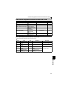
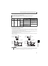
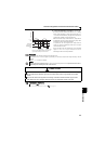
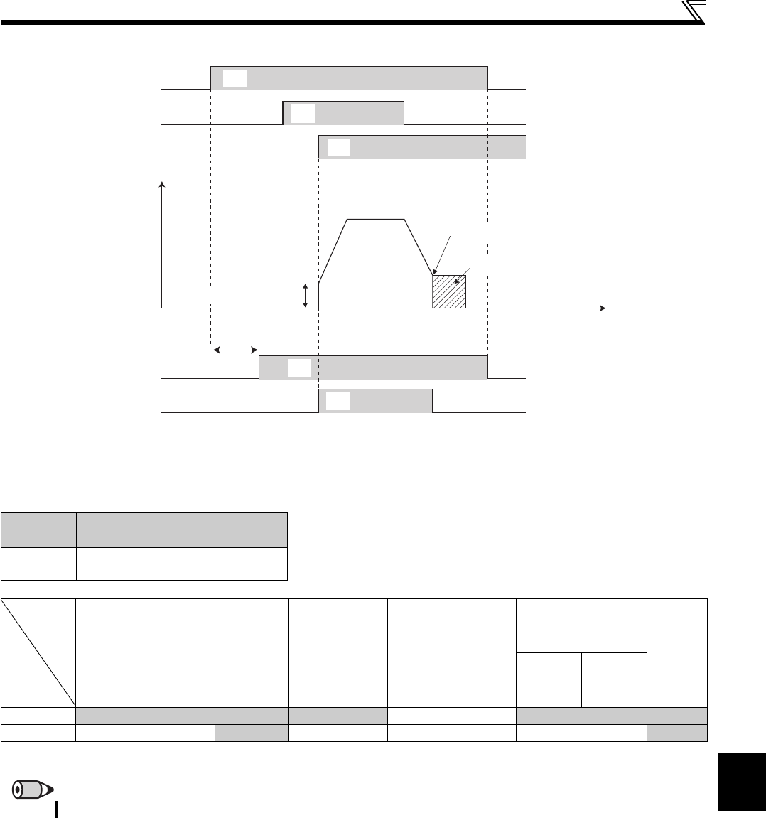
(2) Inverter operation ready signal (RY signal) and inverter running signal (RUN signal)
When the inverter is ready to operate, the output of the operation ready signal (RY) is ON. (It is also ON during inverter running.)
When the output frequency of the inverter rises to or above Pr. 13 Starting frequency , the output of the inverter running signal
(RUN) is turned on. During an inverter stop or DC injection brake operation, the output is off.
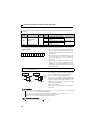
When using the RY and RUN signals, assign functions to Pr.190 or Pr.192 (output terminal selection function) referring to the
table below.
Output
Signal
Pr. 190 to Pr. 192 Setting
Positive logic Negative logic
RY
11 111
RUN
0 100
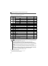
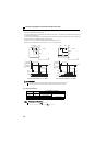
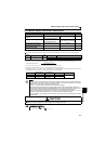
Inverter
Status
Start
Signal
OFF
(during
stop)
Start
Signal ON
(during
stop)
Start
Signal ON
(during
operation)
Under DC
Injection Brake
At Alarm
Occurrence
or MRS Signal ON
(output shutoff)
Automatic Restart after
Instantaneous Power Failure
Coasting
Restarting
Output
signal
Start
signal
ON
Start
signal
OFF
RY ON ON ON ON OFF ON ∗1 ON
RUN OFF OFF
ON OFF OFF OFF ON
∗1 This signal turns OFF during power failure or undervoltage.
REMARKS
The RUN signal (positive logic) is assigned to the terminal RUN in the initial setting.
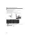
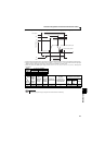
Time
Power supply
Output frequency
STF
RH
RY
Pr. 13 Starting frequency
ON OFF
ON OFF
ON OFF
ON
DC injection brake operation point
DC injection brake operation
RUN
ON OFF
Reset processing