


266
Inspection items
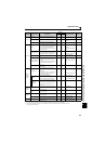
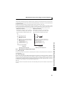
6.1.4 Display of the life of the inverter parts
The self-diagnostic alarm is output when the life span of the control circuit capacitor, cooling fan and each parts of the inrush
current limit circuit is near to give an indication of replacement time.
The life alarm output can be used as a guideline for life judgement.
<Module device numbers and terminals to be checked>
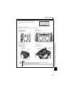
6.1.6 Cleaning
Always run the inverter in a clean status.
When cleaning the inverter, gently wipe dirty areas with a soft cloth immersed in neutral detergent or ethanol.
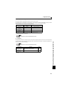
Parts Judgement Level
Main circuit capacitor 85% of the initial capacity
Control circuit capacitor Estimated remaining life 10%
Inrush current limit circuit
Estimated remaining life 10%
(Power on: 100,000 times left)
Cooling fan Less than 50% of the predetermined speed
POINT
Refer to page 229 to perform the life check of the inverter parts.
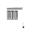
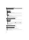
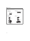
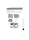
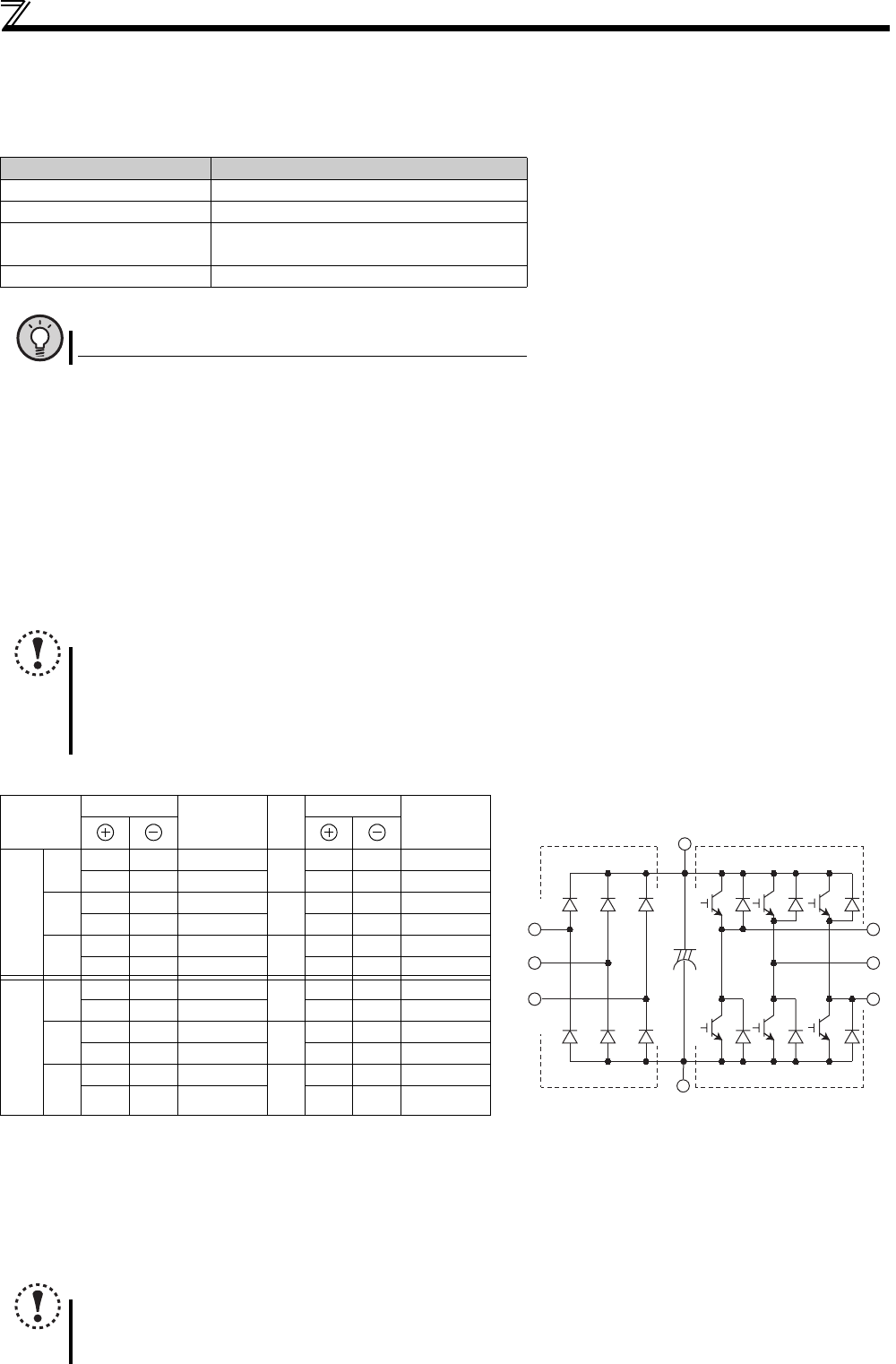
6.1.5 Checking the inverter and converter modules
<Preparation>
(1) Disconnect the external power supply cables (R/L1, S/L2, T/L3) and motor cables (U, V, W).
(2) Prepare a tester. (Use 100Ω range.)
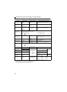
<Checking method>
Change the polarity of the tester alternately at the inverter terminals R/L1, S/L2, T/L3, U, V, W, P/+ and N/-, and check for
continuity.
NOTE
1. Before measurement, check that the smoothing capacitor is discharged.
2. At the time of discontinuity, the measured value is almost
∞. When there is an instantaneous continuity, due to the
smoothing capacitor, the tester may not indicate
∞. At the time of continuity, the measured value is several to
several tens-of ohms depending on the module type, circuit tester type, etc. If all measured values are almost the
same, the modules are without fault.
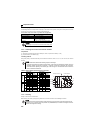
Tester Polarity
Measured
Value
Tester Polarity
Measured
Value
Converter
module
D1
R/L1 P/+ Discontinuity
D4
R/L1 N/− Continuity
P/+ R/L1 Continuity N/− R/L1 Discontinuity
D2
S/L2 P/+ Discontinuity
D5
S/L2 N/− Continuity
P/+ S/L2 Continuity N/− S/L2 Discontinuity
D3∗
T/L3∗ P/+ Discontinuity
D6∗
T/L3∗ N/− Continuity
P/+ T/L3∗ Continuity N/− T/L3∗ Discontinuity
Inverter
module
TR1
UP/+ Discontinuity
TR4
UN/− Continuity
P/+ U Continuity N/− U Discontinuity
TR3
VP/+ Discontinuity
TR6
VN/− Continuity
P/+ V Continuity N/− V Discontinuity
TR5
WP/+ Discontinuity
TR2
WN/− Continuity
P/+ W Continuity N/− W Discontinuity
(Assumes the use of an analog meter.)
* T/L3, D3 and D6 are only for the three-phase power input specification models.
NOTE
Do not use solvent, such as acetone, benzene, toluene and alcohol, as they will cause the inverter surface paint to peel off.
The display, etc. of the operation panel and parameter unit (FR-PU04/FR-PU07) are vulnerable to detergent and alcohol.
Therefore, avoid using them for cleaning.
Converter module Inverter module
D1 D2 D3
D4 D5 D6
TR1 TR3 TR5
TR4 TR6 TR2
U
V
W
R/L1
S/L2
T/L3
C
P/+
N/−