


189
Communication operation and setting
4
PARAMETERS
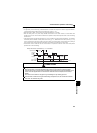
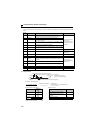
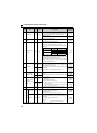
(3) Communication operation presence/absence and data format types
Data communication between the computer and inverter is made in ASCII code (hexadecimal code).
Communication operation presence/absence and data format types are as follows:
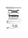
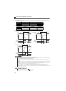
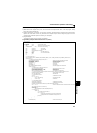
Data writing format
Communication request data from the computer to the inverter 1)
Reply data from the inverter to the computer 3) (No data error detected)
Reply data from the inverter to the computer 3) (With data error)
No. Operation
Run
Command
Operation
Frequency
Multi
command
Parameter
Write
Inverter
Reset
Monitor
Parameter
Read
1)
Communication request is sent to the
inverter in accordance with the user
program in the computer.
A1
A, A2
∗3
A3
A, A2 ∗
3
AB B
2)
Inverter data processing time Present Present Present Present Present Present Present
3)
Reply data from the
inverter (Data 1) is
checked for error)
No error ∗
1
(Request
accepted)
CCC1∗4 C
C ∗
2
E, E1, E2,
E3 ∗
3
E, E2 ∗3
With error
(Request
rejected)
DDD D
D ∗
2
DD
4)
Computer processing delay time 10ms or more
5)
Answer from
computer in response
to reply data 3).
(Data 3) is checked
for error)
No error ∗
1
(No inverter
processing)
Absent Absent
Absent
(C)
Absent Absent
Absent
(C)
Absent (C)
With error
(Inverter outputs
3) again.)
Absent Absent F Absent Absent F F
∗1 In the communication request data from the computer to the inverter, 10ms or more is also required after "no data error (ACK)". (Refer to page 191)
∗2 Reply from the inverter to the inverter reset request can be selected. (Refer to page 195)
∗3 When any of "0.01 to 9998" is set in Pr. 37 and "01" in instruction code, HFF sets data format to A2 or E2. In addition, data format is always A2 and E2
for read or write of Pr. 37.
∗4 At mode error, and data range error, C1 data contains an error code. (Refer to page 199) Except for those errors, the error is returned with data format
D.
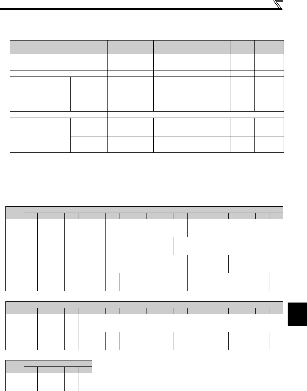
Format
Number of Characters
1 2 3 4 5 6 7 8 9 10 11 12 13 14 15 16 17 18 19
A
ENQ
∗1
Inverter
station
number
∗2
Instruction
code
∗3
Data
Sum
check
∗4
A1
ENQ
∗1
Inverter
station
number
∗2
Instruction
code
∗3
Data
Sum
check
∗4
A2
ENQ
∗1
Inverter
station
number
∗2
Instruction
code
∗3
Data
Sum
check
∗4
A3
ENQ
∗1
Inverter
station
number
∗2
Instruction
code
∗3
Send
data
type
Receive
data
type
Data1 Data2
Sum
check
∗4
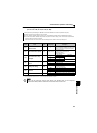
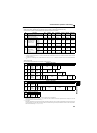
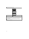
Format
Number of Characters
1 2 3 4 5 6 7 8 9 10 11 12 13 14 15 16 17 18 19
C
ACK
∗1
Inverter
station
number
∗2
∗4
C1
STX
∗1
Inverter
station
number
∗2
Send
data
type
Receive
data
type
Error
code 1
Error
code 2
Data1 Data2
ETX
∗1
Sum
check
∗4
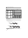
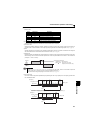
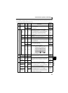
Format
Number of Characters
1 2 3 4 5
D
NAK
∗1
Inverter
station
number
∗2
Error
code
∗4
∗1 Indicate a control code
∗2 Specify the inverter station numbers between H00 and H1F (stations 0 to 31) in hexadecimal.
∗3 Set waiting time. When the Pr. 123 (waiting time setting) is other than "9999", create the communication request data without "waiting time" in the data
format. (The number of characters decreases by 1.)
∗4 CR, LF code
When data is transmitted from the computer to the inverter, codes CR (carriage return) and LF (line feed) are automatically set at the end of a data group
on some computers. In this case, setting must also be made on the inverter according to the computer. Whether the CR and LF codes will be present or
absent can be selected using Pr. 124 (CR, LF selection).