


124
Function assignment of external terminal and control
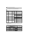
4.10.7 Output current detection function
(Y12 signal, Y13 signal, Pr. 150 to Pr. 153, Pr. 166, Pr. 167)
The above parameters can be set when Pr. 160 Extended function display selection = "0". (Refer to page 162)
The output current during inverter running can be detected and output to the output terminal.
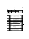
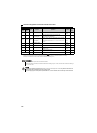
Parameter
Number
Name Initial Value
Setting
Range
Description
150
Output current detection
level
150% 0 to 200% 100% is the rated inverter current.
151
Output current detection
signal delay time
0s 0 to 10s
Output current detection period.
The time from when the output current has risen
above the setting until the output current detection
signal (Y12) is output.
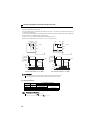
152
Zero current detection
level
5% 0 to 200%
The rated inverter current is assumed to be 100%.
153
Zero current detection
time
0.5s 0 to 1s
Period from when the output current drops below the
Pr. 152
value until the zero current detection signal
(Y13) is output.
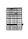
166
Output current detection
signal retention time
0.1s
0 to 10s
Set the retention time when the Y12 signal is ON.
9999
The Y12 signal ON status is retained. The signal is
turned off at the next start.
167
Output current detection
operation selection
0
0
Operation continues when the Y12 signal is ON
1
The inverter is brought to trip when the Y12 signal is
ON. (E.CDO)
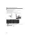
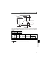
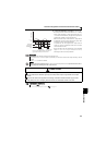
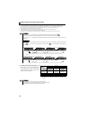
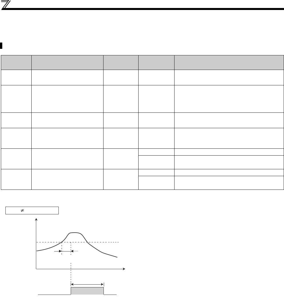
(1) Output current detection
(Y12 signal, Pr. 150, Pr. 151, Pr. 166, Pr. 167 )
The output current detection function can be used for
excessive torque detection, etc.
If the output current remains higher than the Pr. 150 setting
during inverter operation for longer than the time set in Pr.
151, the output current detection signal (Y12) is output from
the inverter's open collector or relay output terminal.
When the Y12 signal turns ON, the ON state is held for the
time set in Pr. 166.
When Pr. 166 = "9999", the ON state is held until a next start.
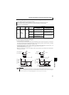
At the Pr. 167 setting of "1", the inverter trips, and the output
current detection fault (E.CDO) is displayed when the Y12
signal turns ON. When fault occurs, the Y12 signal is ON for
the time set in Pr. 166 at the Pr. 166 setting of other than
9999, and remains ON until a reset is made at the Pr. 166
setting of 9999. E.CDO does not occur even if "1" is set in Pr.
167 while Y12 is ON. The Pr. 167 setting is valid after Y12
turns OFF.
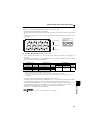
For the Y12 signal, set "12 (positive logic) or 112 (negative
logic)" in Pr. 190 or Pr. 192 (output terminal function selection)
and assign functions to the output terminal.
Time
Pr. 150
OFF
ON
OFF
Output current
detection signal
(Y12)
Pr. 166
Min. 0.1s (initial value)
Output current
Pr. 166 9999, Pr. 167 = 0
Pr. 151