


271
Measurement of main circuit voltages, currents and powers
6
PRECAUTIONS FOR MAINTENANCE AND INSPECTION
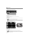
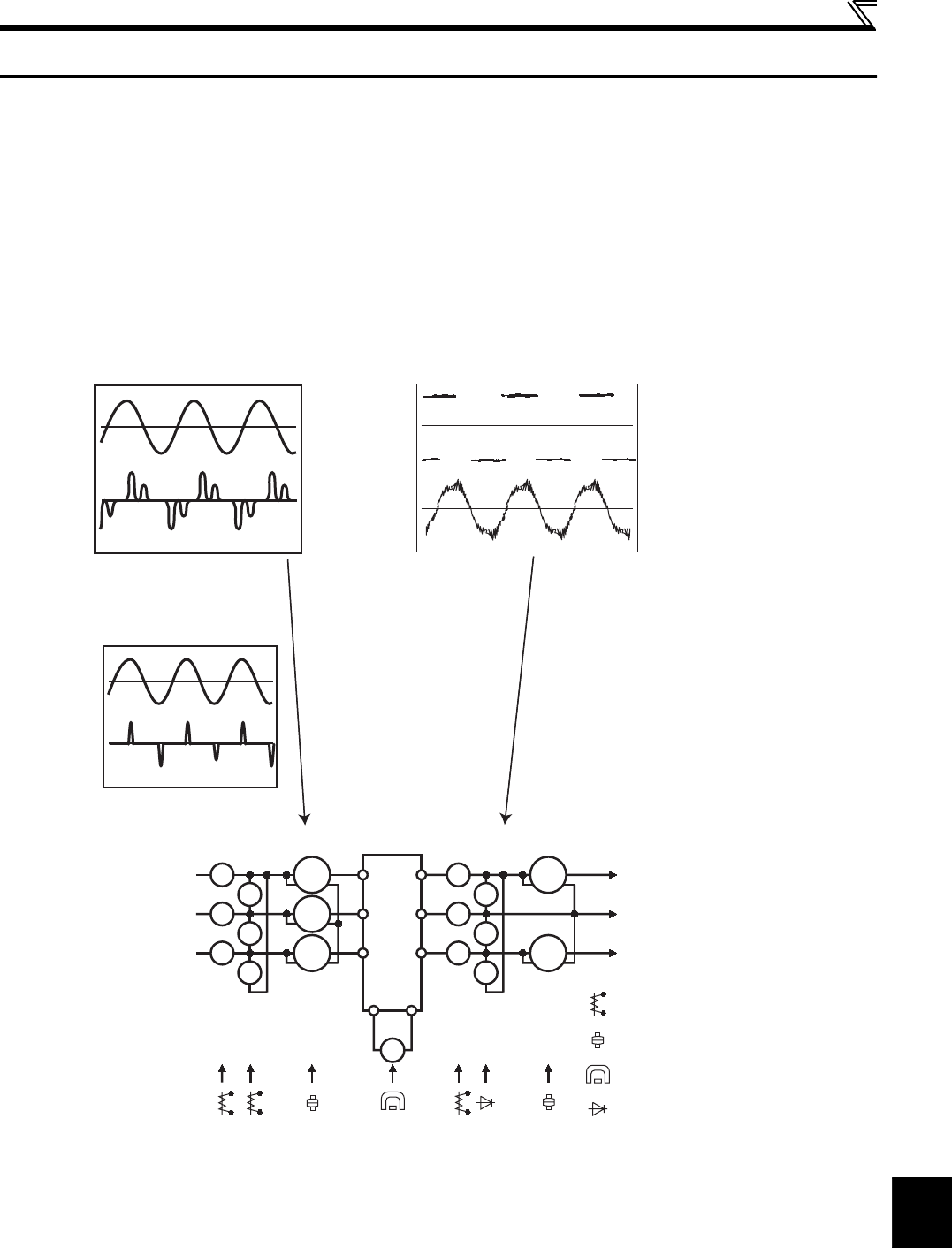
6.2 Measurement of main circuit voltages, currents and powers
Since the voltages and currents on the inverter power supply and output sides include harmonics, measurement data
depends on the instruments used and circuits measured.
When instruments for commercial frequency are used for measurement, measure the following circuits with the instruments
given on the next page.
When installing meters etc. on the inverter output side
When the inverter-to-motor wiring length is large, especially in the 400V class, small-capacity models, the meters and CTs
may generate heat due to line-to-line leakage current. Therefore, choose the equipment which has enough allowance for
the current rating.
To measure and display the output voltage and output current of the inverter, it is recommended to use the AM-5 terminal
output function of the inverter.
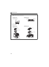
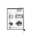
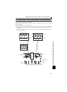
Examples of Measuring Points and Instruments
+-
Ar
∗
∗
∗
∗
∗
∗
As
At
Vr
Vs
Vt
W11
W12
W13
Au
Av
Aw
Vu
Vv
Vw
W21
W22
V
U
V
W
Inverter
Instrument types
: Moving-iron type
: Electrodynamometer type
: Moving-coil type
: Rectifier type
R/L1
S/L2
T/L3
Three-phase
power supply
To the motor
Input voltage
Input current
Output voltage
Output current
Three-phase power input
Single-phase power input
P/+ N/-
∗ At, As, Vt, Vs, W12, W13 are only for the three-phase power input specification models.