


215
Special operation and frequency control
4
PARAMETERS
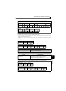
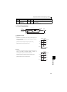
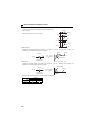
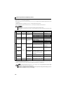
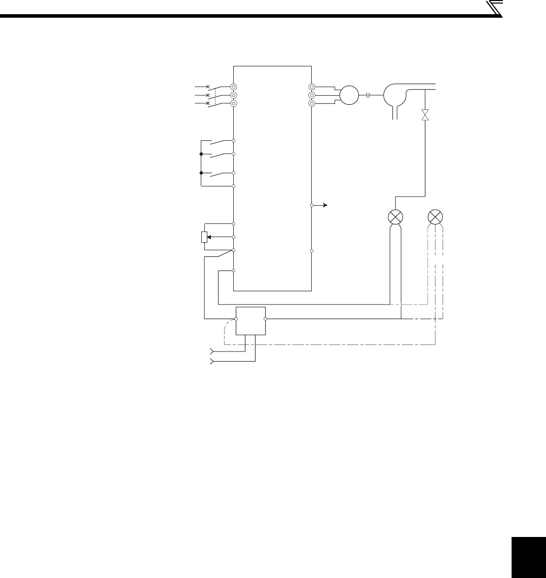
(3) Connection diagram
Sink logic
Pr. 128 = 20
Pr. 182 = 14
Pr. 190 = 15
Pr. 192 = 16
∗1 The power supply must be selected in accordance with the power specifications of the detector used.
∗2 The used output signal terminal changes depending on the Pr. 190 , Pr. 192 (output terminal selection) setting.
∗3 The used input signal terminal changes depending on the Pr. 178 to Pr. 182 (input terminal selection) setting.
∗4 The AU signal need not be input.
Power supply
MCCB
Inverter
Forward rotation
Reverse rotation
PID control selection
Setting Potentiometer
(Set point setting)
0 24V
Power
supply
*1
AC1φ
200/220V 50/60Hz
R/L1
S/L2
T/L3
STF
STR
RH(X14)
*3
SD
10
2
5
4
*4
U
V
W
*2(FUP)RUN
SE
(measured value) 4 to 20mA
Motor
IM
Pump
P
Upper limit
Output signal
common
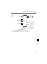
2-wire type
Detector
3-wire type
-
++ +
-
(OUT) (24V)
(COM)