


152
Frequency setting by analog input (terminal 2, 4)
4.16.2 Response level of analog input and noise elimination (Pr. 74)
The above parameter can be set when Pr. 160 Extended function display selection = "0". (Refer to page 162)
Valid for eliminating noise of the frequency setting circuit.
Increase the filter time constant if steady operation cannot be performed due to noise.
A larger setting results in slower response. (The time constant can be set between approximately 1ms to 1s with the setting
of 0 to 8.)
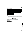
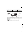
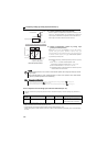
(3) Perform operation by analog input selection
When the pressure or temperature is controlled constantly by a fan,
pump, etc., automatic operation can be performed by inputting the
output signal 4 to 20mADC of the adjuster across the terminals 4-5.
The AU signal must be turned ON to use the terminal 4.
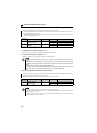
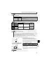
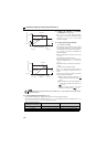
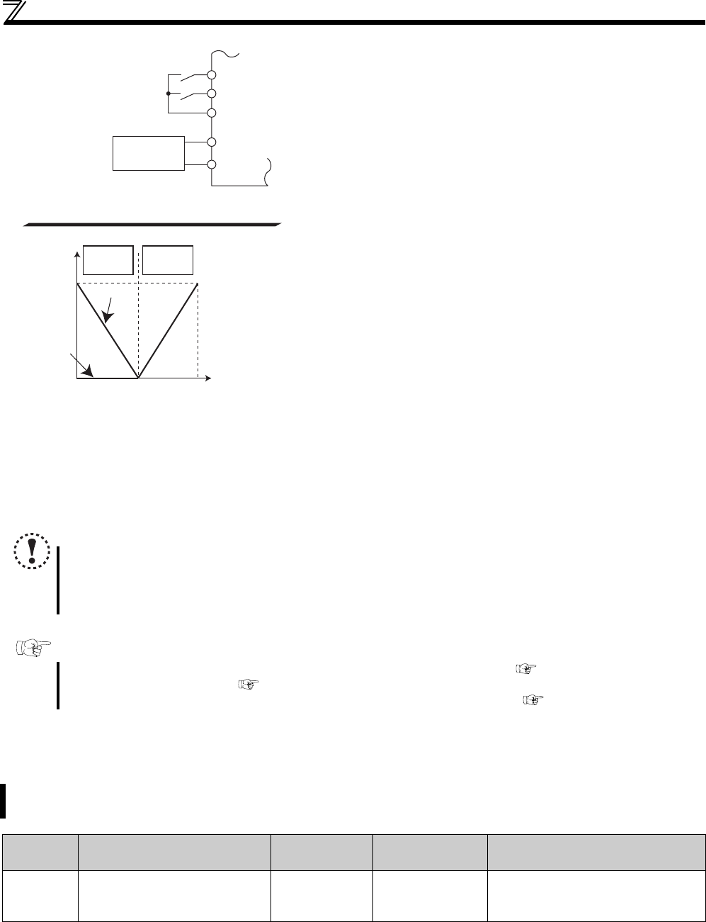
Reversible operation example
(4) Perform forward/reverse rotation by analog input
(polarity reversible operation)
Setting "10" or "11" in Pr. 73 and adjusting Pr. 125 (Pr. 126) Terminal 2
frequency setting gain frequency (Terminal 4 frequency setting gain
frequency) and C2 (Pr. 902) Terminal 2 frequency setting bias frequency to
C7 (Pr.905) Terminal 4 frequency setting gain makes reverse operation
by terminal 2 (terminal 4) valid.
Example)When performing reversible operation by terminal 2 (0 to 5V)
input
1) Set "11" in Pr. 73 to make reversible operation valid.
Set frequency at maximum analog input in Pr. 125 (Pr. 903)
2) Set 1/2 of the value set in C4 (Pr. 903) in C3 (Pr. 902).
3) Reversible operation is performed when 0 to 2.5VDC is input and
forward rotation when 2.5 to 5VDC.
NOTE
When reversible operation is set, be aware of reverse rotation operation when analog input stops (only the start
signal is input).
When reversible operation is valid, reversible operation (0 to 4mA: reverse operation, 4mA to 20mA: forward
operation) is performed by terminal 4 in the initial setting.
Parameters referred to
Pr. 125 Terminal 2 frequency setting gain frequency, Pr. 126 Terminal 4 frequency setting gain frequency Refer to page 153
Pr. 561 PTC thermistor protection level Refer to page 100
C2 (Pr. 902) Terminal 2 frequency setting bias frequency to C7 (Pr. 905) Terminal 4 frequency setting gain Refer to page 153
The time constant of the primary delay filter can be set for the external frequency command (analog input (terminal 2, 4)
signal).
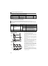
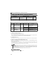
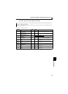
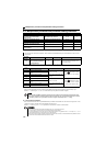
Parameter
Number
Name Initial Value Setting Range Description
74 Input filter time constant
1 0 to 8
Primary delay filter time constant for the
analog input.
A larger setting results in a larger filter.
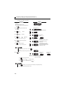
STF
Inverter
Forward rotation
Frequency setting
SD
4
5
AU
Connection diagram using terminal 4 (4 to 20mADC)
4 to 20mADC
Current input
equipment
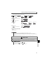
2.5V
C3(Pr.902)
Pr. 125
C4(Pr.903)
C2(Pr. 902)
5V
Reverse
rotation
Forward
rotation
Set frequency (Hz)
Terminal 2
input (V)
0
Frequency setting signal
Not
reversible
Reversible