


253
5
TROUBLESHOOTING
Causes and corrective actions
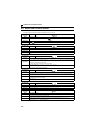
(3) Alarm
When an alarm occurs, the output is not shut off. You can also output an alarm signal by making parameter setting.
(Set "98" in Pr. 190 or Pr. 192 (output terminal function selection). Refer to page 119 ).
(4) Fault
When a fault occurs, the inverter trips and a fault signal is output.
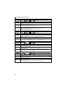
Operation panel
indication
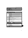
SA
FR-PU04
FR-PU07
——
Name
Safety stop
Description
Appears when safety stop function is activated (during output shutoff).
Check point
If the indication appears when safety stop function is not used, check that shorting wires between S1 and SC, S2 and
SC are connected.
Corrective action
If the indication appears when safety stop function is not used, short between S1 and SC, S2 and SC with shorting
wires.
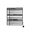
Operation panel
indication
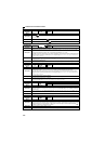
FN
FR-PU04
FR-PU07
FN
Name
Fan fault
Description
For the inverter that contains a cooling fan, appears on the operation panel when the cooling fan stops due to
an alarm or different operation from the setting of Pr. 244 Cooling fan operation selection.
Check point
Check the cooling fan for an alarm.
Corrective action
Check for fan alarm. Please contact your sales representative.
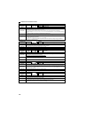
Operation panel
indication
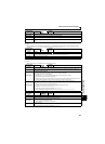
E.OC1
FR-PU04
FR-PU07
OC During Acc
Name
Overcurrent trip during acceleration
Description
When the inverter output current reaches or exceeds approximately 200% of the rated current during acceleration, the
protective circuit is activated and the inverter trips.
Check point
1. Check for sudden acceleration.
2. Check that the downward acceleration time is not long in vertical lift application.
3. Check for output short-circuit/ground fault.
4. Check that the Pr. 3 Base frequency setting is not 60Hz when the motor rated frequency is 50Hz.
5. Check that stall prevention operation is appropriate.
6. Check that regeneration is not performed frequently. (Check that the output voltage becomes larger than the V/F
reference value at regeneration and overcurrent occurs due to increase in motor current.)
Corrective action
1. Increase the acceleration time. (Shorten the downward acceleration time in vertical lift application.)
2. When "E.OC1" is always lit at starting, disconnect the motor once and start the inverter.
If "E.OC1" is still lit, contact your sales representative.
3. Check the wiring to make sure that output short circuit/ground fault does not occur.
4. Set 50Hz in Pr. 3 Base frequency. (Refer to page 85)
5. Perform stall prevention operation appropriately. (Refer to page 79).
6. Set base voltage (rated voltage of the motor, etc.) in Pr. 19 Base frequency voltage. (Refer to page 85)
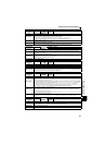
Operation panel
indication
E.OC2
FR-PU04
FR-PU07
Stedy Spd OC
Name
Overcurrent trip during constant speed
Description
When the inverter output current reaches or exceeds approximately 200% of the rated current during constant speed
operation, the protective circuit is activated and the inverter trips.
Check point
1. Check for sudden load change.
2. Check for output short-circuit/ground fault.
3. Check that stall prevention operation is appropriate.
Corrective action
1. Keep load stable.
2. Check the wiring to make sure that output short circuit/ground fault does not occur.
3. Perform stall prevention operation appropriately. (Refer to page 79).