


38
EMC and leakage currents
3.1 EMC and leakage currents
3.1.1 Leakage currents and countermeasures
Capacitances exist between the inverter I/O cables, other cables and earth and in the motor, through which a leakage current
flows. Since its value depends on the static capacitances, carrier frequency, etc., low acoustic noise operation at the
increased carrier frequency of the inverter will increase the leakage current. Therefore, take the following measures. Select
the earth leakage current breaker according to its rated sensitivity current, independently of the carrier frequency setting.
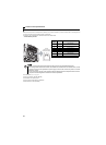
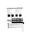
(1) To-earth (ground) leakage currents
Leakage currents may flow not only into the inverter's own line but also into the other lines through the earth (ground) cable,
etc. These leakage currents may operate earth (ground) leakage circuit breakers and earth leakage relays unnecessarily.
Suppression technique
If the carrier frequency setting is high, decrease the Pr. 72 PWM frequency selection setting.
Note that motor noise increases. Selecting Pr. 240 Soft-PWM operation selection makes the sound inoffensive.
By using earth leakage circuit breakers designed for harmonic and surge suppression in the inverter's own line and other
line, operation can be performed with the carrier frequency kept high (with low noise).
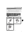
To-earth (ground) leakage currents
Take caution as long wiring will increase the leakage current. Decreasing the carrier frequency of the inverter reduces the
leakage current.
Increasig the motor capacity increases the leakage current. The leakage current of the 400V class is larger than that of
the 200V class.
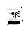
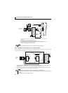
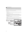
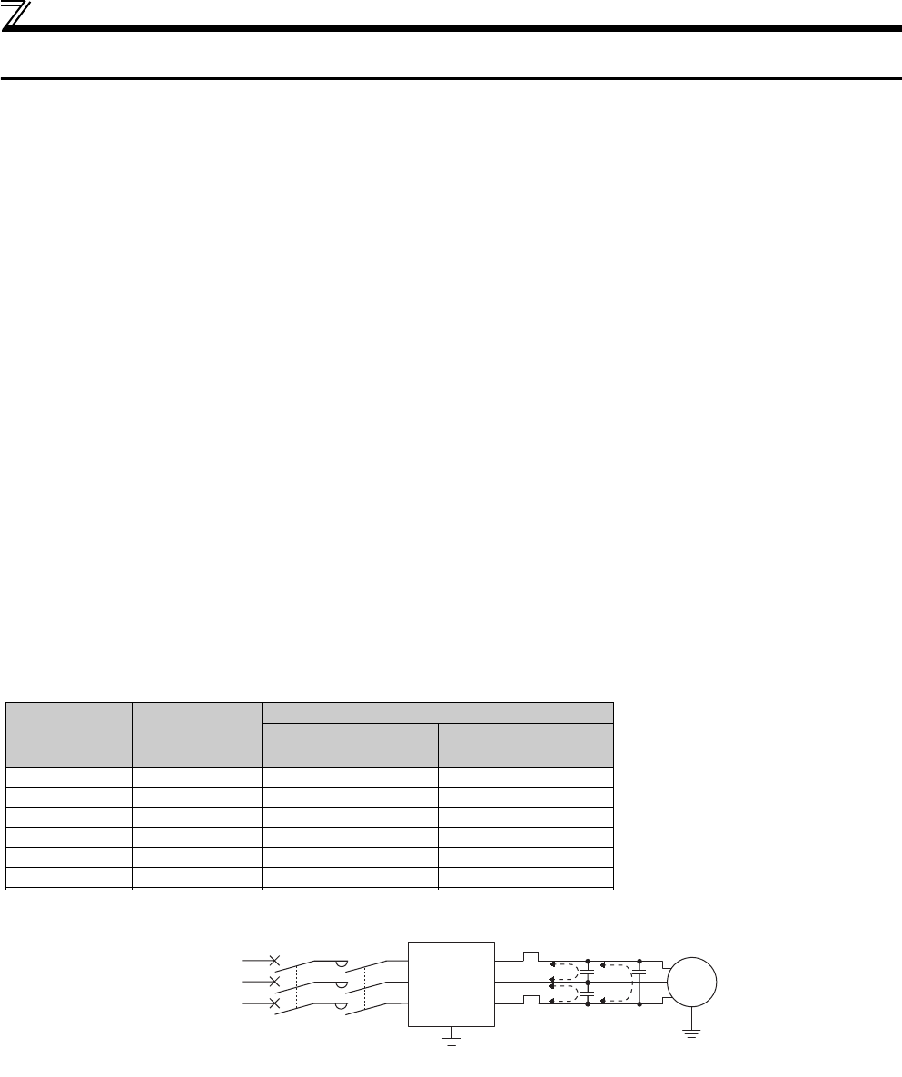
(2) Line-to-line leakage currents
Harmonics of leakage currents flowing in static capacitances between the inverter output cables may operate the external
thermal relay unnecessarily. When the wiring length is long (50m (164.04feet) or more) for the 400V class small-capacity model
(FR-D740-160 or less), the external thermal relay is likely to operate unnecessarily because the ratio of the leakage current to
the rated motor current increases.
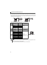
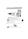
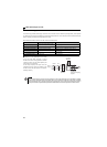
Line-to-line leakage current data example
*The leakage currents of the 200V class are about a half.
Measures
Use Pr. 9 Electronic thermal O/L relay.
If the carrier frequency setting is high, decrease the Pr. 72 PWM frequency selection setting.
Note that motor noise increases. Selecting Pr. 240 Soft-PWM operation selection makes the sound inoffensive.
To ensure that the motor is protected against line-to-line leakage currents, it is recommended to use a temperature
sensor to directly detect motor temperature.
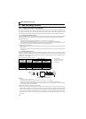
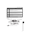
Installation and selection of moulded case circuit breaker
Install a moulded case circuit breaker (MCCB) on the power receiving side to protect the wiring of the inverter input side.
Select the MCCB according to the inverter input side power factor (which depends on the power supply voltage, output
frequency and load). Especially for a completely electromagnetic MCCB, one of a slightly large capacity must be selected
since its operation characteristic varies with harmonic currents. (Check it in the data of the corresponding breaker.) As an
earth leakage current breaker, use the Mitsubishi earth leakage current breaker designed for harmonics and surge
suppression.
Motor Capacity
(kW (HP))
Rated Motor
Current (A)
Leakage Current (mA) *
Wiring length 50m
(164.04feet)
Wiring length 100m
(328.08feet)
0.4 (1/2) 1.1 620 1000
0.75 (1) 1.9 680 1060
1.5 (2) 3.5 740 1120
2.2 (3) 4.1 800 1180
3.7 (5) 6.4 880 1260
5.5 (7.5) 9.7 980 1360
Motor: SF-JR 4P
Carrier frequency: 14.5kHz
Used wire: 2mm
2
, 4 cores
Cabtyre cable
Power
supply
Thermal relay
Line-to-line static
capacitances
MCCB MC
Line-to-line leakage currents path
Motor
Inverter
IM