


258
Causes and corrective actions
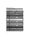
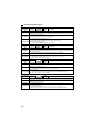
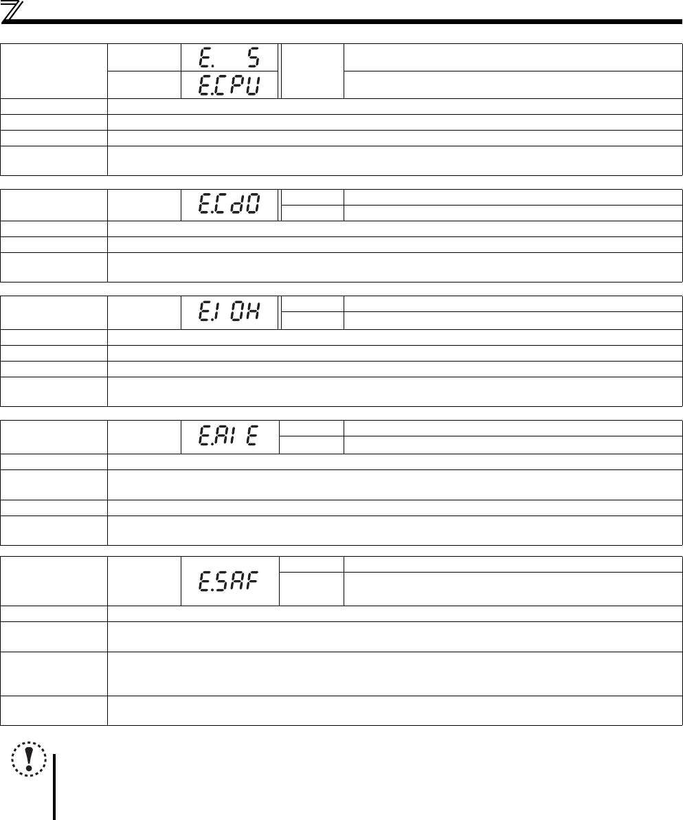
Operation panel
indication
E.5
FR-PU04
FR-PU07
Fault 5
E.CPU CPU Fault
Name
CPU fault
Description
Stops the inverter output if the communication fault of the built-in CPU occurs.
Check point
Check for devices producing excess electrical noises around the inverter.
Corrective action
Take measures against noises if there are devices producing excess electrical noises around the inverter.
Please contact your sales representative.
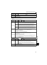
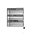
Operation panel
indication
E.CDO
FR-PU04 Fault 14
FR-PU07 OC detect level
Name
Output current detection value exceeded
Description
This function is activated when the output current exceeds the Pr. 150 Output current detection level setting.
Check point
Check the settings of Pr. 150 Output current detection level, Pr. 151 Output current detection signal delay time, Pr. 166 Output
current detection signal retention time, Pr. 167 Output current detection operation selection. (Refer to page 124)
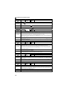
Operation panel
indication
E.IOH
FR-PU04 Fault 14
FR-PU07 Inrush overheat
Name
Inrush current limit circuit fault
Description
This function is activated when the resistor of the inrush current limit circuit overheats. The inrush current limit circuit fault
Check point
Check that frequent power ON/OFF is not repeated.
Corrective action
Configure a circuit where frequent power ON/OFF is not repeated.
If the problem still persists after taking the above measure, please contact your sales representative.
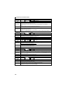
Operation panel
indication
E.AIE
FR-PU04 Fault 14
FR-PU07 Analog in error
Name
Analog input fault
Description
Appears if voltage(current) is input to terminal 4 when the setting in Pr.267 Terminal 4 input selection and the setting of
voltage/current input switch are different.
Check point
Check the setting of Pr. 267 Terminal 4 input selection and voltage/current input switch. (Refer to page 150).
Corrective action
Either give a frequency command by current input or set Pr. 267 Terminal 4 input selection, and voltage/current input
switch to voltage input.
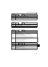
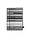
Operation panel
indication
E.SAF
FR-PU04 Fault 14
FR-PU07
Fault
E.SAF
Name
Safety circuit fault
Description
Appears when safety circuit is malfunctioning.
Appears when one of the lines between S1 and SC, or between S2 and SC is opened.
Check point
If the indication appears when safety stop function is not used, check that shorting wires between S1 and SC, S2
and SC are connected.
Check that the safety relay module is properly connected.
Corrective action
If the indication appears when safety stop function is not used, short between S1 and SC, S2 and SC with shorting
wires.
NOTE
If protective functions of E.ILF, E.AIE, E.IOH, E.PTC, E.CDO, E.SAF are activated when using the FR-PU04, "Fault 14"
is displayed.
Also when the faults history is checked on the FR-PU04, the display is "E.14".
If faults other than the above appear, contact your sales representative.