


21
2
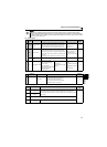
WIRING
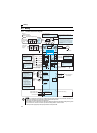
Control circuit specifications
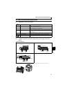
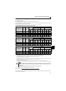
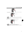
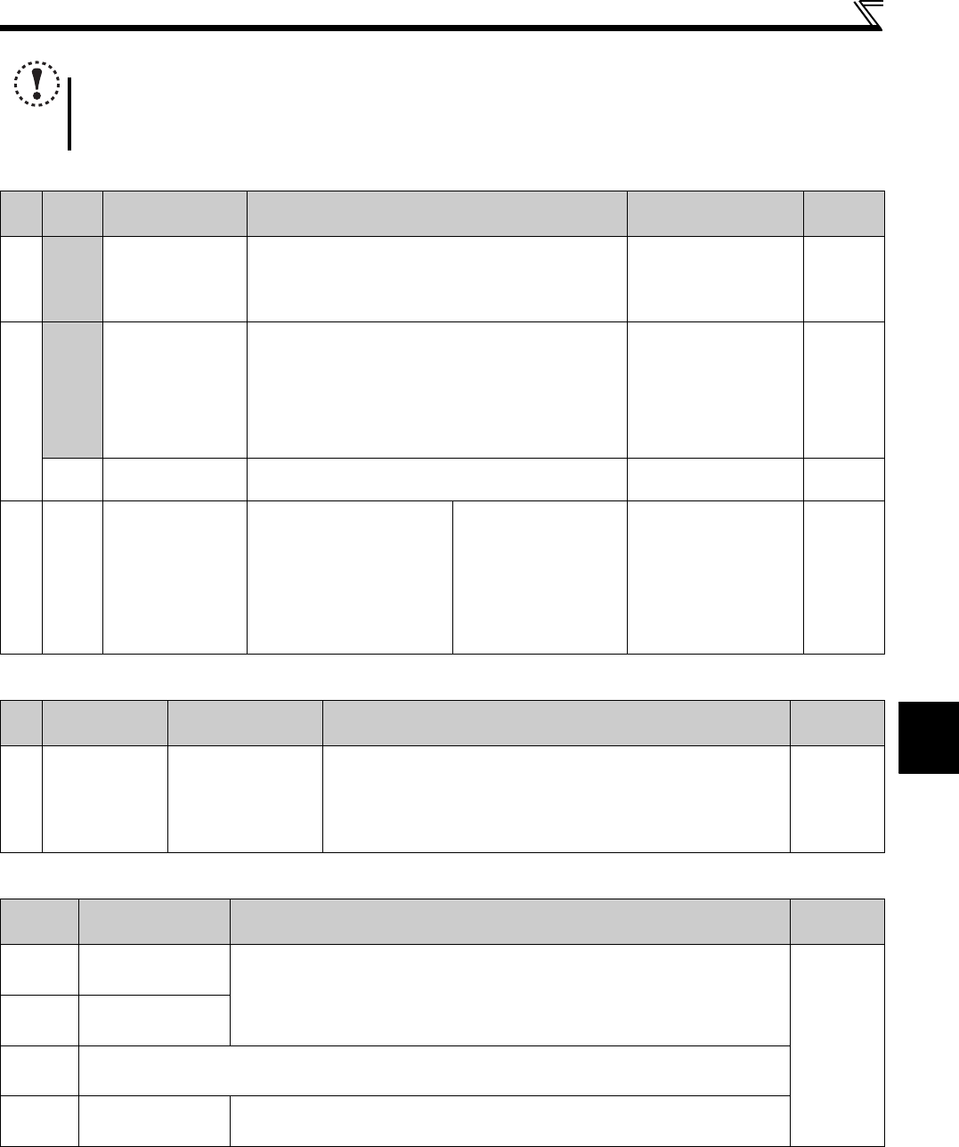
(2) Output signal
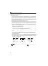
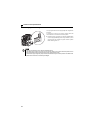
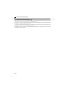
(3) Communication
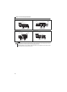
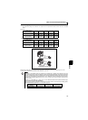
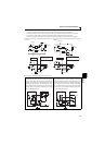
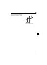
(4) Safety stop signal
NOTE
Set Pr. 267 and a voltage/current input switch correctly, then input analog signals in accordance with the settings.
Applying a voltage with voltage/current input switch in "I" position (current input is selected) or a current with switch in
"V" position (voltage input is selected) could cause component damage of the inverter or analog circuit of output
devices. (Refer to page 150 for details.)
Type
Terminal
Symbol
Terminal Name Description Rated Specifications
Reference
Page
Relay
A, B, C
Relay output (fault
output)
1 changeover contact output indicates that the inverter
protective function has activated and the output stopped.
Fault: discontinuity across B-C (continuity across A-C),
Normal: continuity across B-C (discontinuity across A-C)
Contact capacity:230VAC
0.3A
(power factor =0.4)
30VDC 0.3A
119
Open collector
RUN Inverter running
Switched low when the inverter output frequency is equal to
or higher than the starting frequency (initial value 0.5Hz).
Switched high during stop or DC injection brake operation.
(Low indicates that the open collector output transistor is on
(conducts).
High indicates that the transistor is off (does not conduct).)
Permissible load 24VDC
(maximum 27VDC) 0.1A
(a voltage drop is 3.4V
maximum when the signal
is on)
119
SE
Open collector output
common
Common terminal of terminal RUN. — —
Analog
AM Analog signal output
Select one e.g. output
frequency from monitor
items. Not output during
inverter reset.
The output signal is
proportional to the magnitude
of the corresponding
monitoring item.
Output item:
Output frequency (initial
setting)
Output signal 0 to
10VDC
Permissible load current
1mA
(load impedance 10kΩ or
more)
Resolution 8 bit
128
Type
Terminal
Symbol
Terminal Name Description
Reference
Page
RS-485
— PU connector
With the PU connector, communication can be made through RS-485.
Conforming standard: EIA-485 (RS-485)
Transmission format: Multidrop link
Communication speed: 4800 to 38400bps
Overall length: 500m (1640.42feet)
180
Terminal
Symbol
Terminal Name Description
Reference
Page
S1
Inverter output shutoff
(Line 1)
Inverter output is shutoff depending on shorting/opening between S1 and SC, S2 and SC.
At initial state, terminal S1 and S2 are shorted to terminal SC with a shorting wire.
When using the safety stop function, remove this shorting wire, and connect to a safety
relay module.
—
S2
Inverter output shutoff
(Line 2)
SO For manufacturer setting
SC
Output shutoff terminal
common
Common terminal for terminals S1, S2. Connected to terminal SD inside of the inverter.