


119
Function assignment of external terminal and control
4
PARAMETERS
4.10.5 Output terminal function selection (Pr. 190, Pr. 192)
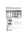
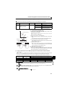
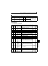
(1) Output signal list
You can set the functions of the output terminals.
Refer to the following table and set the parameters: (0 to 99: positive logic, 100 to 199: negative logic)
You can change the functions of the open collector output terminal and relay output terminal.
Parameter
Number
Name
Initial
Value
Initial Signal Setting Range
190
RUN terminal
function selection
Open collector
output terminal
0 RUN (inverter running)
0, 1, 3, 4, 7, 8, 11 to 16, 25, 26,
46, 47, 64, 70, 80, 90, 91, 93*, 95,
96, 98, 99, 100, 101, 103, 104,
107, 108, 111 to 116, 125, 126,
146, 147, 164, 170, 180, 190,
191, 193*, 195, 196, 198, 199,
9999
192
A,B,C terminal
function selection
Relay
output terminal
99 ALM (fault output)
* "93" and "193" can not be set in Pr. 192.
The above parameters can be set when Pr. 160 Extended function display selection = "0". (Refer to page 162)
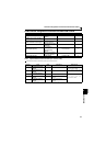
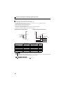
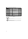
Setting
Signal
Function Operation
Related
Parameter
Refer
to
Page
Positive
logic
Negative
logic
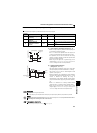
0 100 RUN Inverter running
Output during operation when the inverter output frequency
rises to or above Pr. 13 Starting frequency.
—
121
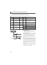
1 101 SU Up to frequency ∗1
Output when the output frequency is reached to the set frequency.
Pr. 41 123
3 103 OL Overload alarm Output while stall prevention function is activated.
Pr. 22, Pr. 23,
Pr. 66
79
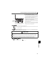
4104FU
Output frequency
detection
Output when the output frequency reaches the frequency
set in Pr. 42 (Pr. 43 for reverse rotation).
Pr. 42, Pr. 43 123
7107RBP
Regenerative brake
pre-alarm
Output when 85% of the regenerative brake duty set in Pr.
70 is reached.
Pr. 70 110
8108THP
Electronic thermal O/L
relay pre-alarm
Output when the electronic thermal value reaches 85% of
the trip level. (Electronic thermal relay function protection
(E.THT/E.THM) activates, when the value reached 100%.
Pr. 9, Pr. 51 100
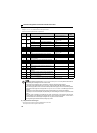
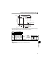
11 111 RY
Inverter operation
ready
Output when reset process is completed (when the inverter
can be started by switching the start signal on or while it is
running) after powering on inverter.
—
121
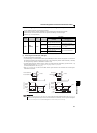
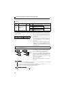
12 112 Y12
Output current
detection
Output when the output current is higher than the Pr. 150
setting for longer than the time set in Pr. 151 .
Pr. 150,
Pr. 151
124
13 113 Y13 Zero current detection
Output when the output power is lower than the Pr. 152
setting for longer than the time set in Pr. 153 .
Pr. 152,
Pr. 153
124
14 114 FDN PID lower limit
Output when the feedback value falls below the lower limit
of PID control.
Pr. 127 to
Pr. 134
Pr. 575 to Pr.
577
21215 115 FUP PID upper limit
Output when the feedback value rises above the upper limit
of PID control
16 116 RL
PID forward/reverse
rotation output
Output when forward rotation is performed in PID control.
25 125 FAN Fan fault output Output at the time of a fan fault. Pr. 244 228
26 126 FIN
Heatsink overheat
pre-alarm
Output when the heatsink temperature reaches about 85%
of the heatsink overheat protection providing temperature.
—
255
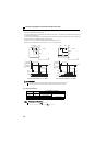
46 146 Y46
During deceleration at
occurrence of power
failure
Output when the power failure-time deceleration function is
executed.
(retained until release)
Pr. 261 142
47 147 PID
During PID control
activated
Output during PID control.
Pr. 127 to
Pr. 134
Pr. 575 to Pr.
577
212
64 164 Y64 During retry Output during retry processing.
Pr. 65 to
Pr. 69
144
70 170
SLEEP
PID output interruption
Output when the PID output interruption function is
executed.
Pr. 127 to Pr.
134,
Pr. 575 to Pr.
577
212
80 180 For manufacturer setting