


110
Motor brake and stop operation
4.9.2 Selection of a regenerative brake (Pr. 30, Pr. 70)
The above parameters can be set when Pr. 160 Extended function display selection = "0". (Refer to page 162)
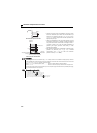
(1) When using the brake resistor (MRS type, MYS type), brake unit (FR-BU2), power regeneration
common converter (FR-CV), and high power factor converter (FR-HC).
Set Pr. 30 to "0" (initial value). The Pr. 70 setting is invalid.
At this time, the regenerative brake duty is as follows.
FR-D720-025 to 165, FR-D720S-025 or more..................3%
FR-D720-238 and 318, FR-D740-012 or more .................2%
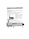
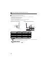
Assign the inverter operation enable signal (X10) to the contact input terminal. To make protective coordination with the
FR-HC and FR-CV, use the inverter operation enable signal to shut off the inverter output.
Input the RDY signal of the FR-HC (RDYB signal of the FR-CV).
For the terminal used for X10 signal input, assign its function by setting "10" (X10) to any of Pr. 178 to Pr. 182.
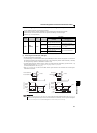
(2) Brake resistor (MYS type) used at 100% torque/6%ED (FR-D720-165 only)
Set "1" in Pr. 30.
Set "6%" in Pr. 70.
REMARKS
For the
FR-D720-238 and 318, FR-D740-120 and 160
, when the Pr. 12 setting is the following, changing the Pr. 71 Applied motor
setting automatically changes the Pr. 12 setting. Therefore, it is not necessary to change the Pr. 12 setting.
(a) When 4% (initial value) is set in Pr. 12
The Pr. 12 setting is automatically changed to 2% if the Pr. 71 value is changed from the value selecting the standard motor
(0, 3, 23, 40, 43) to the value selecting the constant torque motor (1, 13, 50, 53).
(b) When 2% is set in Pr. 12
The Pr. 12 setting is automatically changed to 4% (initial value) if the Pr. 71 value is changed from the value selecting the
constant-torque motor (1, 13, 50, 53) to the value selecting the standard motor (0, 3, 23, 40, 43).
Even if the value of Pr. 12 setting is increased, braking torque is limited so that the output current is within the rated inverter
current.
CAUTION
As stop holding torque is not produced, install a mechanical brake.
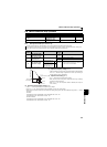
Parameters referred to
Pr. 13 Starting frequency Refer to page 98
Pr. 71 Applied motor Refer to page 103
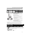
When making frequent starts/stops, use the optional brake resistor (MRS type, MYS type), high-duty brake resistor
(FR-ABR) and brake unit (FR-BU2) to increase the regenerative brake duty.
Use a power regeneration common converter (FR-CV) for continuous operation in regeneration status.
Use the high power factor converter (FR-HC) to reduce harmonics, improve the power factor, or continuously use the
regenerative status.
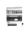
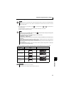
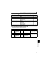
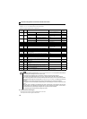
Parameter
Number
Name
Initial
Value
Setting
Range
Description
30
Regenerative function
selection
0
0
Without regenerative function,
Brake resistor (MRS type, MYS type),
Brake unit (FR-BU2)
Power regeneration common converter (FR-CV)
High power factor converter (FR-HC)
1
Brake resistor (MYS type) used at 100% torque/6%ED,
High-duty brake resistor (FR-ABR)
2
High power factor converter (FR-HC) when automatic
restart after instantaneous power failure is selected
70
Special regenerative
brake duty
0% 0 to 30%
Brake duty when using the high-duty brake resistor
(FR-ABR)