


205
Communication operation and setting
4
PARAMETERS
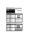
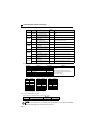
Write holding register data (H06 or 06)
Can write the description of 1) system environment variabls and 4) inverter parameters assigned to the holding
register area (refer to the register list ( page 209)).
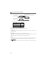
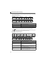
Query message
Normal response (Response message)
Query message setting
Description of normal response
1) to 4) (including CRC check) of the normal response are the same as those of the query message.
No response is made for broadcast communication.
1) Slave Address 2) Function 3) Register Address 4) Preset Data CRC Check
(8bit)
H06
(8bit)
H
(8bit)
L
(8bit)
H
(8bit)
L
(8bit)
L
(8bit)
H
(8bit)
1) Slave Address 2) Function 3) Register Address 4) Preset Data CRC Check
(8bit)
H06
(8bit)
H
(8bit)
L
(8bit)
H
(8bit)
L
(8bit)
L
(8bit)
H
(8bit)
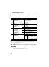
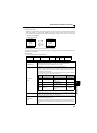
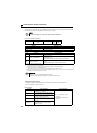
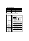
Message Setting Description
1)Slave Address
Address to which the message will be sent
Setting of address 0 enables broadcast communication
2) Function Set H06.
3)Register Address
Address of the holding register to which data will be written
Register address = Holding register address (decimal)-40001
For example, setting of register address 0001 writes data to the holding register
address 40002.
4)Preset Data
Data that will be written to the holding register
The written data is always 2 bytes.
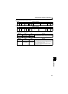
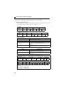
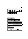
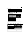
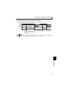
Example: To write 60Hz (H1770) to 40014 (running frequency RAM) at slave address 5 (H05).
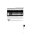
NOTE
For broadcast communication, no response is returned in reply to a query. Therefore, the next query must be
made when the inverter processing time has elapsed after the previous query.
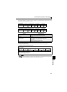
Query message
Normal response (Response message)
Same data as the query message
Slave Address Function Register Address Preset Data CRC Check
H05
(8bit)
H06
(8bit)
H00
(8bit)
H0D
(8bit)
H17
(8bit)
H70
(8bit)
H17
(8bit)
H99
(8bit)