


255
5
TROUBLESHOOTING
Causes and corrective actions
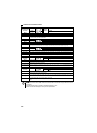
∗1 Resetting the inverter initializes the internal thermal integrated data of the electronic thermal relay function.
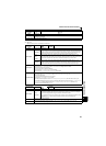
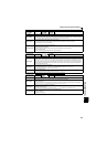
Operation panel
indication
E.THT
FR-PU04
FR-PU07
Inv. Overload
Name
Inverter overload trip (electronic thermal relay function)
Description
If the temperature of the output transistor element exceeds the protection level under the condition that a current not
less than the rated inverter current flows and overcurrent trip does not occur (200% or less), the electronic thermal
relay activates to stop the inverter output. (Overload capacity 150% 60s, 200% 0.5s)
Check point
1. Check that acceleration/deceleration time is not too short.
2. Check that torque boost setting is not too large (small).
3. Check that load pattern selection setting is appropriate for the load pattern of the using machine.
4. Check the motor for use under overload.
5. Check for too high surrounding air temperature.
Corrective action
1. Increase acceleration/deceleration time.
2. Adjust the torque boost setting.
3. Set the load pattern selection setting according to the load pattern of the using machine.
4. Reduce the load weight.
5. Set the surrounding air temperature to within the specifications.
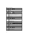
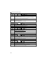
Operation panel
indication
E.THM
FR-PU04
FR-PU07
Motor Ovrload
Name
Motor overload trip (electronic thermal relay function) ∗1
Description
The electronic thermal relay function in the inverter detects motor overheat due to overload or reduced cooling
capability during constant-speed operation, and pre-alarm (TH display) is output when the integrated value reaches
85% of the Pr. 9 Electronic thermal O/L relay setting, and the protection circuit is activated to stop the inverter output
when the integrated value reaches the specified value. When running a special motor such as a multi-pole motor or
multiple motors, provide a thermal relay on the inverter output side since such motor(s) cannot be protected by the
electronic thermal relay function.
Check point
1. Check the motor for use under overload.
2. Check that the setting of Pr. 71 Applied motor for motor selection is correct. (Refer to page 103).
3. Check that stall prevention operation setting is correct.
Corrective action
1. Reduce the load weight.
2. For a constant-torque motor, set the constant-torque motor in Pr. 71 Applied motor.
3. Check that stall prevention operation setting is correct. (Refer to page 79).
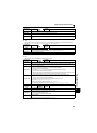
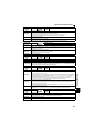
Operation panel
indication
E.FIN
FR-PU04
FR-PU07
H/Sink O/Temp
Name
Fin overheat
Description
If the heatsink overheats, the temperature sensor is actuated and the inverter trips.
The FIN signal can be output when the temperature becomes approximately 85% of the heatsink overheat protection
operation temperature.
For the terminal used for the FIN signal output, assign the function by setting "26 (positive logic) or 126 (negative
logic)" in Pr. 190 or Pr. 192 (output terminal function selection). (Refer to page 119).
Check point
1. Check for too high surrounding air temperature.
2.
Check for heatsink clogging.
3. Check that the cooling fan is not stopped (Check that is not displayed on the operation panel).
Corrective action
1. Set the surrounding air temperature to within the specifications.
2. Clean the heatsink.
3. Replace the cooling fan.