


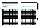


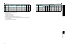
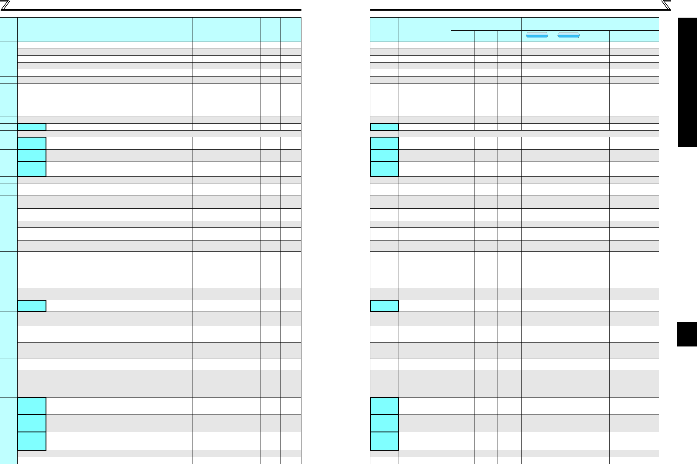
Parameter listParameter list
64
4
PARAMETERS
Parameter List
Life diagnosis
255 Life alarm status display (0 to 15) 1 0 229 255 3F BF 2 ×××
256 Inrush current limit circuit life display (0 to 100%) 1% 100% 229 256 40 C0 2 × × ×
257 Control circuit capacitor life display (0 to 100%) 1% 100% 229 257 41 C1 2 ×××
258 Main circuit capacitor life display (0 to 100%) 1% 100% 229 258 42 C2 2 × × ×
259 Main circuit capacitor life measuring 0, 1 (2, 3, 8, 9) 1 0 229 259 43 C3 2
— 260 PWM frequency automatic switchover 0, 1 1 0 148 260 44 C4 2
Power failure
stop
261 Power failure stop selection 0, 1, 2 1 0 142 261 45 C5 2
— 267 Terminal 4 input selection 0, 1, 2 1 0 150 267 4B CB 2 ×
— 268 Monitor decimal digits selection 0, 1, 9999 1 9999 128 268 4C CC 2
— 269 Parameter for manufacturer setting. Do not set. 269 Parameter for manufacturer setting. Do not set.
— 295 Magnitude of frequency change setting
0, 0.01, 0.10, 1.00,
10.00
0.01 0 240 295 67 E7 2
Password
function
296 Password lock level 1 to 6, 101 to 106, 9999 1 9999 163 296 68 E8 2 ×
297 Password lock/unlock
1000 to 9999 (0 to 5,
9999)
1 9999 163 297 69 E9 2 ×
— 298 Frequency search gain 0 to 32767, 9999 1 9999 136 298 6A EA 2 ×
— 299
Rotation direction detection selection
at restarting
0, 1, 9999 1 0 136 299 6B EB 2
RS-485 communication
338
Communication operation command
source
0, 1 1 0 176 338 26 A6 3 ∗7 ∗7
339
Communication speed command
source
0, 1, 2 1 0 176 339 27 A7 3 ∗7 ∗7
340 Communication startup mode selection 0, 1, 10 1 0 175 340 28 A8 3 ∗7 ∗7
342
Communication EEPROM write
selection
0, 1 1 0 187 342 2A AA 3
343 Communication error count — 1 0 200 343 2B AB 3 × × ×
Second motor
constant
450 Second applied motor 0, 1, 9999 1 9999 103 450 32 B2 4
Remote
Output
495 Remote output selection 0, 1, 10, 11 1 0 126 495 5F DF 4
496 Remote output data 1 0 to 4095 1 0 126 496 60 E0 4 ×××
— 502
Stop mode selection at communication
error
0, 1, 2 1 0
184,
200
502 02 82 5
Maintenance
503 Maintenance timer 0 (1 to 9998) 1 0 233 503 03 83 5 ×××
504
Maintenance timer alarm output set
time
0 to 9998, 9999 1 9999 233 504 04 84 5 ×
Communication
549 Protocol selection 0, 1 1 0 200 549 31 B1 5 ∗7 ∗7
551
PU mode operation command source
selection
2, 4, 9999 1 9999 176 551 33 B3 5 ∗7 ∗7
Current average
time monitor
555 Current average time 0.1 to 1s 0.1s 1s 234 555 37 B7 5
556 Data output mask time 0 to 20s 0.1s 0s 234 556 38 B8 5
557
Current average value monitor signal
output reference current
0 to 500A 0.01A
Rated
inverter
current
234 557 39 B9 5
— 561 PTC thermistor protection level 0.5 to 30kΩ , 9999 0.01Ω 9999 100 561 3D BD 5 ×
— 563 Energization time carrying-over times (0 to 65535) 1 0 128 563 3F BF 5 ×××
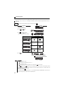
Func-
tion
Parameter
Name Setting Range
Minimum
Setting
Increments
Initial
Value
Refer
to
Page
Customer
Setting
Parameter
Remarks
Instruction Code
Control Mode-based
Correspondence Table
Parameter
Read Write
Extended
Copy Clear
All clear
V/F
V/F
V/F
GP
MFVC
GP
MFVC
GP
MFVC