


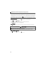
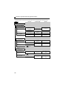

168
Selection of operation mode and operation location
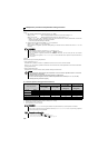
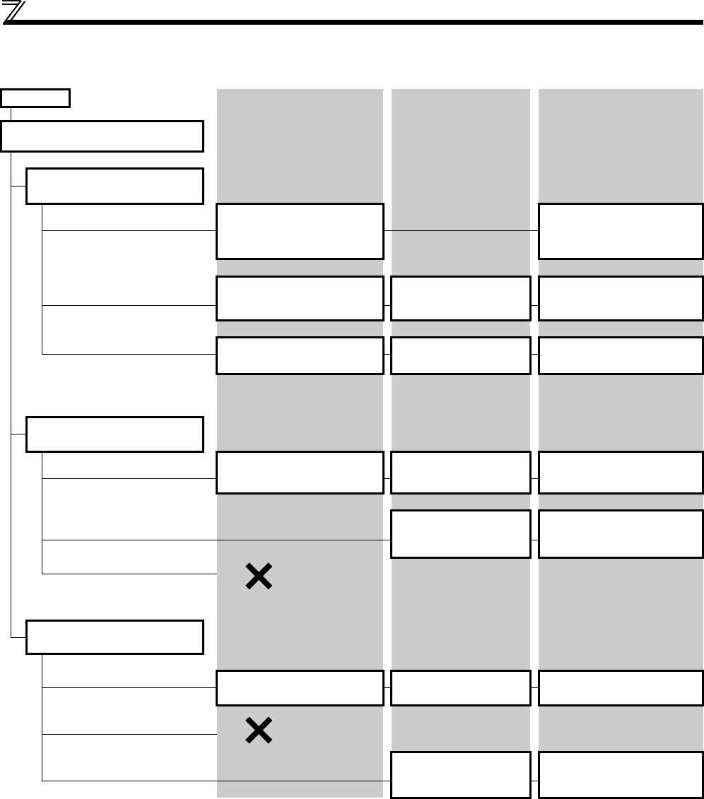
(3) Operation mode selection flow
In the following flowchart, select the basic parameter setting and terminal connection related to the operation mode.
START
Connection Parameter setting Operation
Where is the start command
source?
From outside (STF/STR terminal)
Where is the frequency
command source?
From outside (Terminal 2, 4, JOG,
multi-speed, etc.)
STF (forward rotation)
/STR (reverse rotation)
(Refer to page 113.)
Terminal 2, 4-5 (analog), RL, RM,
RH, JOG, etc.
Frequency setting terminal ON
STF(STR)-ON
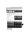
From the operation panel
(digital setting)
STF (forward rotation)
/STR (reverse rotation)
(Refer to page 113)
Pr. 79 = "3"
(External/PU combined
operation 1)
Operation panel, PU digital setting
STF(STR)-ON
From communication
(PU connector (RS-485 communication)
STF (forward rotation)
/STR (reverse rotation)
(Refer to page 113)
Pr. 338 = "1"
Pr. 340 = "1"
Communication frequency setting
command sending
STF(STR)-ON
From the operation panel (RUN/FWD/
REV key)
Where is the frequency
command source?
From outside (terminal 2, 4, JOG,
multi-speed, etc.)
Terminal 2, 4-5 (analog), RL, RM,
RH, JOG, etc.
Pr. 79 = "4"
(external/PU combined
operation 2)
Frequency setting terminal ON
RUN/FWD/REV key-ON
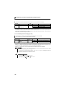
From the operation panel
(digital setting)
Pr. 79 = "1"
(fixed to PU operation)
Digital setting
RUN/FWD/REV key-ON
From communication
(PU connector (RS-485 communication)
From communication (
PU connector (RS-
485 communication
))
Where is the frequency
command source?
From outside (terminal 2, 4, JOG,
multi-speed, etc.)
Terminal 2, 4-5 (analog), RL, RM,
RH, JOG, etc.
Pr. 339 = "1"
Pr. 340 = "1"
Frequency setting terminal ON
Communication start command
sending
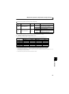
From the operation panel
(digital setting)
From communication
(PU connector (RS-485 communication)
Pr. 340 = "1"
Communication frequency setting
command sending
Communication start command
sending
Disabled
Disabled