


3
1
OUTLINE
Inverter and peripheral devices
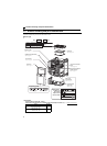
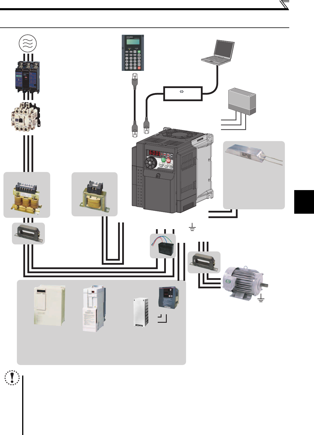
1.2 Inverter and peripheral devices
NOTE
The life of the inverter is influenced by surrounding air temperature. The surrounding air temperature should be as low as
possible within the permissible range. This must be noted especially when the inverter is installed in an enclosure.
(
Refer to page 8
)
Wrong wiring might lead to damage of the inverter. The control signal lines must be kept fully away from the main
circuit to protect them from noise. (Refer to page 14)
Do not install a power factor correction capacitor, surge suppressor or capacitor type filter on the inverter output
side. This will cause the inverter to trip or the capacitor and surge suppressor to be damaged. If any of the above
devices are connected, immediately remove them.
Electromagnetic wave interference
The input/output (main circuit) of the inverter includes high frequency components, which may interfere with the
communication devices (such as AM radios) used near the inverter. In this case, install the FR-BIF optional capacitor type
filter (for use in the input side only) or FR-BSF01 or FR-BLF common mode filter to minimize interference.
(Refer to page 40).
Refer to the instruction manual of each option and peripheral devices for details of peripheral devices.
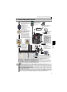
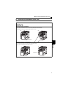
Three-phase AC power supply
Use within the permissible power supply
specifications of the inverter. To ensure
safety, use a moulded case circuit breaker,
earth leakage circuit breaker or magnetic
contactor to switch power ON/OFF.
Magnetic contactor (MC)
Install the magnetic contactor to ensure
safety. Do not use this magnetic contactor
to start and stop the inverter. Doing so will
cause the inverter life to be shorten.
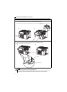
Noise filter
(FR-BSF01, FR-BLF)
Install a noise filter to reduce the
electromagnetic noise generated
from the inverter.
Effective in the range from about
1MHz to 10MHz. A wire should be
wound four turns at a maximum.
Earth (Ground)
Devices connected to the output
Do not install a power factor correction capacitor,
surge suppressor or capacitor type filter on the output
side of the inverter. When installing a moulded case
circuit breaker on the output side of the inverter,
contact each manufacturer for selection of the
moulded case circuit breaker.
The regenerative braking capability
of the inverter can be exhibited fully.
Install this as required.
Power supply harmonics
can be greatly suppressed.
Install this as required.
High power factor
converter (FR-HC)
Power regeneration
common converter
(FR-CV)
R/L1S/L2T/L3
P1
P/+
P/+
N/-
UW
P/+
PR
V
Great braking capability
is obtained.
Install this as required.
Reactor (FR-HAL, FR-HEL option)
Reactors (option) must be used when
power harmonics measures are taken,
the power factor is to be improved or the
inverter is installed near a large power
supply system (500kVA or more). The
inverter may be damaged if you do not
use reactors. Select the reactor according
to the model. Remove the jumpers across
terminals P/+ and P1 to connect the DC reactor.
Inverter (FR-D700)
Noise filter
(FR-BSF01, FR-BLF)
Moulded case circuit breaker
(MCCB) or earth leakage circuit
breaker (ELB), fuse
The breaker must be selected carefully
since an in-rush current flows in the
inverter at power on.
Install a noise filter to reduce
the electromagnetic noise
generated from the inverter.
Effective in the range from
about 1MHz to 10MHz. When
more wires are passed
through, a more effective result
can be obtained. A wire should
be wound four turns or more.
Earth (Ground)
To prevent an electric shock, always earth (ground)
the motor and inverter. For reduction of induction noise
from the power line of the inverter, it is recommended
to wire the earth (ground) cable by returning it to the
earth (ground) terminal of the inverter.
AC reactor (FR-HAL)
DC reactor (FR-HEL)
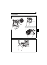
Parameter unit (FR-PU07)
By connecting the connection cable
(FR-CB2) to the PU connector,
operation can be performed from
FR-PU07.
Capacitor type
filter
(FR-BIF)
P/+
P/+
PR
PR
Brake unit
(FR-BU2)
Reduces the
radio noise.
Resistor unit (FR-BR)
Discharging resistor (GZG, GRZG)
RS-232C - RS-485 converter is
required when connecting to PC
with RS-232C interface.
Motor
Earth (Ground)
S1
S2
SC
Safety relay module
Required for
compliance with
safety standard.
RS-485 RS-232C
Converter
(Refer to page 281)
(Refer to page 4)
(Refer to page 44)
(Refer to page 180)
(Refer to page 29)
Brake resistor (FR-ABR,
MRS type, MYS type)
Braking capability can be
improved.
(FR-D720-025 or more,
FR-D740-012 or more,
FR-D720S-025 or more)
(Refer to page 31)