


30
Control circuit specifications
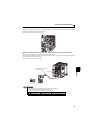
RS-485 communication
When the PU connector is connected with a personal, FA or other computer by a communication cable, a user program can
run and monitor the inverter or read and write to parameters.
The protocol can be selected from Mitsubishi inverter and Modbus RTU.
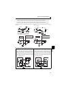
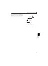
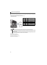
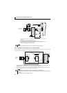
PU connector pin-outs
For further details, refer to page 180.
Conforming standard: EIA-485 (RS-485)
Transmission form: Multidrop link
Communication speed: Maximum 38400 bps
Overall extension: 500m (1640feet)
Pin
Number
Name Description
1) SG
Earth (ground)
(connected to terminal 5)
2) — Parameter unit power supply
3) RDA Inverter receive+
4) SDB Inverter send-
5) SDA Inverter send+
6) RDB Inverter receive-
7) SG
Earth (ground)
(connected to terminal 5)
8) — Parameter unit power supply
NOTE
Pins No. 2 and 8 provide power to the parameter unit. Do not use these pins for RS-485 communication.
When making RS-485 communication between the FR-D700 series, FR-E500 series and FR-S500 series, incorrect
connection of pins No.2 and 8 (parameter unit power supply) of the above PU connector may result in the inverter
malfunction or failure.
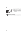
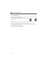
Do not connect the PU connector to the computer's LAN board, FAX modem socket or telephone modular connector.
The product could be damaged due to differences in electrical specifications.
8) 1)to
Inverter
(receptacle side)
Viewed from bottom