


256
Causes and corrective actions
∗ Available only for three-phase power input specification model.
Operation panel
indication
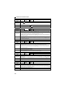
E.ILF
FR-PU04 Fault 14
FR-PU07 Input phase loss
Name
Input phase loss ∗
Description
Inverter trips when function valid setting (=1) is selected in Pr. 872 Input phase loss protection selection and one phase of
the three phase power input is lost. (Refer to page 146).
It may function if phase-to-phase voltage of the three-phase power input becomes largely unbalanced.
When the setting of Pr. 872 Input phase loss protection selection is the initial value (Pr. 872 ="0"), this warning does not
occur.
Check point
Check for a break in the cable for the three-phase power supply input.
Check that phase-to-phase voltage of the three-phase power input is not largely unbalanced.
Corrective action
Wire the cables properly.
Repair a break portion in the cable.
Check the Pr. 872 Input phase loss protection selection setting.
Set Pr. 872 = "0" (without input phase loss protection) when three-phase input voltage is largely unbalanced.
Operation panel
indication
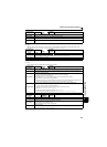
E.OLT
FR-PU04
FR-PU07
Stll Prev STP (OL shown during stall prevention operation)
Name
Stall prevention
Description
If the output frequency has fallen to 1Hz by stall prevention operation and remains for 3s, a fault (E.OLT) appears and
the inverter trips. OL appears while stall prevention is being activated.
Check point
Check the motor for use under overload. (Refer to page 80).
Corrective action
Reduce the load weight. (Check the Pr. 22 Stall prevention operation level setting.)
Operation panel
indication
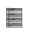
E.BE
FR-PU04
FR-PU07
Br. Cct. Fault
Name
Brake transistor alarm detection
Description
When a brake transistor alarm has occurred due to the large regenerative energy from the motor etc., the brake
transistor alarm is detected and the inverter trips.
In this case, the inverter must be powered off immediately.
Check point
Reduce the load inertia.
Check that the frequency of using the brake is proper.
Check that the brake resistor selected is correct.
Corrective action
Replace the inverter.
Operation panel
indication
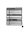
E.GF
FR-PU04
FR-PU07
Ground Fault
Name
Output side earth (ground) fault overcurrent at start
Description
The inverter trips if an earth (ground) fault overcurrent flows at start due to an earth (ground) fault that occurred on
the inverter's output side (load side). Whether this protective function is used or not is set with Pr. 249 Earth (ground)
fault detection at start. When the setting of Pr. 249 Earth (ground) fault detection at start is the initial value (Pr. 249 ="0"),
this warning does not occur.
Check point
Check for a ground fault in the motor and connection cable.
Corrective action
Remedy the ground fault portion.
Operation panel
indication
E.LF
FR-PU04
FR-PU07
E.LF
Name
Output phase loss
Description
This function stops the inverter output if one of the three phases (U, V, W) on the inverter's output side (load side) is
lost. Whether the protective function is used or not is set with Pr. 251 Output phase loss protection selection.
Check point
Check the wiring. (Check that the motor is normal.)
Check that the capacity of the motor used is not smaller than that of the inverter.
Corrective action
Wire the cables properly.
Check the Pr. 251 Output phase loss protection selection settting.