


151
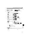
Frequency setting by analog input (terminal 2, 4)
4
PARAMETERS
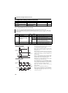
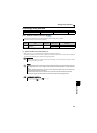
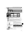
Refer to the following table and set Pr. 73 and Pr. 267.
( indicates main speed setting)
The terminal used for the AU signal input, set "4" in Pr. 178 to Pr. 182 (input terminal function selection) to assign functions.
NOTE
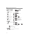
Set Pr. 267 and a voltage/current input switch correctly, then input an analog signal in accordance with the setting.
Incorrect setting as in the table below could cause component damage. Incorrect settings other than below can
cause abnormal operation.
Pr.73
Setting
Terminal 2
Input
Terminal 4 Input Reversible
Operation
AU signal
0 0 to 10V
OFF —
Not function
1
(initial value)
0 to 5V
10
0 to 10V
Yes
11
0 to 5V
0
—
ON
According to the Pr. 267 setting
0:4 to 20mA (initial value)
1:0 to 5V
2:0 to 10V
Not function
1
(initial value)
10
— Yes
11
- : invalid
NOTE
Turn the AU signal on to make terminal 4 valid.
Make sure that the parameter and switch settings are the same. Different setting may cause a fault, failure or
malfunction.
Use Pr. 125 (Pr. 126) (frequency setting gain) to change the maximum output frequency at input of the maximum output
frequency command voltage (current). At this time, the command voltage (current) need not be input.
Also, the acceleration/deceleration time, which is a slope up/down to the acceleration/deceleration reference
frequency, is not affected by the change in Pr. 73 setting.
When Pr. 561 PTC thermistor protection level ≠"9999", terminal 2 is not available for analog frequency command.
Changing the terminal assignment using Pr. 178 to Pr. 182 (input terminal function selection) may affect the other
functions. Make setting after confirming the function of each terminal.
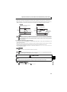
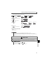
(2) Perform operation by analog input selection
The frequency setting signal inputs 0 to 5VDC (or 0 to 10VDC) across
the terminals 2-5. The 5V (10V) input is the maximum output.
The power supply 5V can be input by either using the internal power
supply or preparing an external power supply. Prepare an external
power supply to input the power supply 10V. For the built-in power
supply, terminals 10-5 provide 5VDC output.
When inputting 10VDC to the terminal 2, set "0" or "10" in Pr. 73. (The
initial value is 0 to 5V)
Setting "1 (0 to 5VDC)" or "2 (0 to 10VDC)" in Pr. 267 and a voltage/
current input switch in the "V" position changes the terminal 4 to the
voltage input specification. When the AU signal turns ON, the terminal
4 input becomes valid.
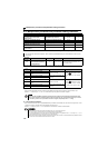
REMARKS
The wiring length of the terminal 10, 2, 5 should be 30m (98.42feet) at maximum.
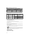
Setting Causing Component Damage
Operation
Switch setting Terminal input
I (current input) Voltage input
This could cause component damage to the analog signal output circuit of
signal output devices.
(electrical load in the analog signal output circuit of signal output devices increases)
V (voltage input) Current input
This could cause component damage of the inverter signal input circuit.
(output power in the analog signal output circuit of signal output devices increases)
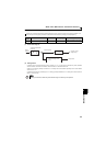
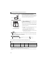
STF
Inverter
Forward rotation
Frequency setting
0 to 5VDC
SD
10
2
5
Connection diagram using terminal 2 (0 to 5VDC)
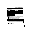
STF
Inverter
Forward rotation
0 to 10VDC
SD
Connection diagram using terminal 2 (0 to 10VDC)
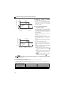
Frequency
setting
2
5
Voltage input
equipment
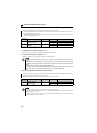
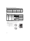
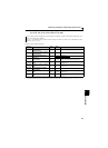
Terminal
Inverter Built-in
Power Supply
Voltage
Frequency
Setting
Resolution
Pr.73
(terminal 2 input
power)
10 5VDC 0.12Hz/60Hz 0 to 5VDC input