


4-81190-00601-02 Rev. E
Garmin G600 Pilot’s Guide
Foreword
Sec 1
System
Sec 2
PFD
Sec 3
MFD
Sec 4
Hazard
Avoidance
Sec 5
Additional
Features
Sec 6
Annun.
& Alerts
Sec 7
Symbols
Sec 8
Glossary Appendix A
Appendix B
Index
the edge. The same antenna is used for both transmitting and receiving. The
returned signal is then processed and displayed on the G600 MFD.
Radar detection is a two-way process that requires 12.36 micro-seconds for
the transmitted microwave pulses to travel out and back for each nautical mile
of target range. It takes 123.6 micro-seconds for a transmitted pulse to make the
round trip if a target is 10 NM away.
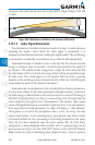
The GWX 68 weather radar should be used to avoid severe weather, not
for penetrating severe weather. The decision to fly into an area of radar targets
depends on target intensity, spacing between the targets, aircraft capabilities and
pilot experience. Pulse type weather radar detects only precipitation, not clouds
or turbulence. The display may indicate clear areas between intense returns, but
this does not necessarily mean it is safe to fly between them. Only Doppler radar
can detect turbulence.
Airborne weather radar has other capabilities beyond weather detection. It
also has the ability to detect and provide distance to objects on the ground, such
as, cities, mountains, coastlines, rivers, lakes, and oceans.
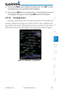
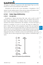
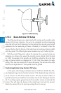
4.10.1.2 Antenna Beam Illumination
It is important to understand the concept of the antenna beam illumination.
The radar beam is much like the beam of a spotlight. The farther the beam
travels, the wider it gets. The radar is only capable of “seeing” what is inside the
boundaries of the beam.
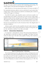
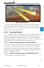
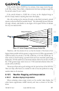
Figure 4-67 Radar Beam from 12 inch Antenna
The vertical dimensions of the radar beam are shown in the figure above and
the same holds true for the horizontal dimensions. In other words, the beam will
be as wide as it is tall. Note that it is possible not to see areas of precipitation on
the radar display because of the antenna tilt setting. With the antenna tilt set to
zero in this illustration, the beam overshoots the precipitation at 15 NM. The