


5-32
Garmin G600 Pilot’s Guide
190-00601-02 Rev. E
Foreword
Sec 1
System
Sec 2
PFD
Sec 3
MFD
Sec 4
Hazard
Avoidance
Sec 5
Additional
Features
Sec 6
Annun.
& Alerts
Sec 7
Symbols
Sec 8
GlossaryAppendix A
Appendix B
Index
Fly the aircraft manually and crosscheck the GDU 620 attitude indication
with the standby attitude indicator and other sources of attitude information
(airspeed, heading, altitude, etc.).
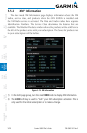
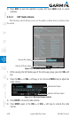
5.6.2 Heading
You are able to control your selected autopilot heading with the GDU 620 by
using the heading bug.
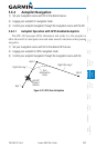
1) Press the HDG key on the PFD and turn the PFD knob to set the desired
heading. When the PFD knob is turned, the Selected Heading box will appear
and remain for three seconds after the knob stops moving.
2) Engage your autopilot in Heading Hold mode.
3) Continue to control your selected autopilot heading by adjusting the heading
bug.
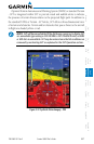
Selected Heading Box
Figure 5-28 Adjusting the Heading Bug
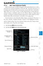
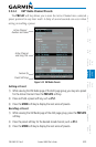
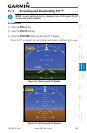
5.6.3 Altitude Capture (Optional Interface)
The altitude selector function is a separately purchased option which works
with the autopilot. At the set altitude, the autopilot will go from a Vertical Speed
Mode (a climb or descent) to an Altitude Capture mode where it will hold the
selected altitude.
1) Select the desired altitude on the GDU 620 by pressing the ALT key and rotating
the PFD knob so the Altitude bug is at the desired altitude.
2) Engage the autopilot in altitude capture mode and select the desired vertical
speed (if able) on the autopilot controller.
3) The autopilot will command a climb or descent at the selected vertical speed
(on the autopilot controller) and capture the selected altitude.
NOTE: The selected Vertical Speed bug on the GDU 620 will not control
the autopilot vertical speed. The autopilot vertical speed must be selected
directly on the autopilot controller.