


2-5190-00601-02 Rev. E
Garmin G600 Pilot’s Guide
Foreword
Sec 1
System
Sec 2
PFD
Sec 3
MFD
Sec 4
Hazard
Avoidance
Sec 5
Additional
Features
Sec 6
Annun.
& Alerts
Sec 7
Symbols
Sec 8
Glossary Appendix A
Appendix B
Index
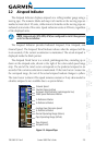
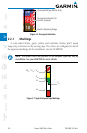
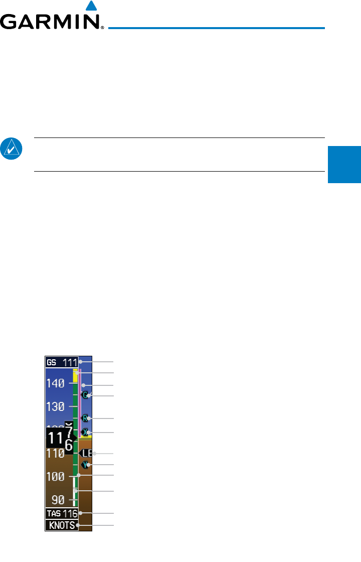
2.2 Airspeed Indicator
The Airspeed Indicator displays airspeed on a rolling number gauge using a
moving tape. The numeric labels and major tick marks on the moving tape are
marked at intervals of 10 units, while minor tick marks on the moving tape are
indicated at intervals of five units. Speed indication starts at 20 knots, regardless
of the displayed units.
NOTE
:
Airspeed units (KTS, MPH, KPH) are configured to match the approved
units for the installation.
The Airspeed Indicator provides Indicated Airspeed, True Airspeed, and
Ground Speed. The Airspeed Trend Indicator shows what the airspeed will be
in six seconds, if the current acceleration is maintained. The actual airspeed is
displayed inside the black pointer.
The Airspeed Trend Vector is a vertical, pink/magenta line, extending up or
down on the airspeed scale, shown to the right of the color-coded speed range
strip. The end of the trend vector corresponds to the predicted airspeed in six
seconds if the current acceleration is maintained. If the trend vector crosses into
the overspeed range, the text of the actual airspeed readout changes to yellow.
The trend vector is absent if the speed remains constant or if any data needed to
calculate airspeed is not available due to a system failure.
Ground Speed
Caution Range (yellow)
Airspeed Trend Indicator (pink/magenta line)
Glide Speed Reference Marker
Vr Reference Marker
Vx Reference Marker
Vy Reference Marker
Landing Gear Extension Speed
Normal Operating Range (Green)
Flaps Operating Range (White)
True Airspeed
Airspeed Units
Figure 2-5 Airspeed Tape