


2-9190-00601-02 Rev. E
Garmin G600 Pilot’s Guide
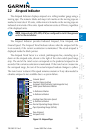
Foreword
Sec 1
System
Sec 2
PFD
Sec 3
MFD
Sec 4
Hazard
Avoidance
Sec 5
Additional
Features
Sec 6
Annun.
& Alerts
Sec 7
Symbols
Sec 8
Glossary Appendix A
Appendix B
Index
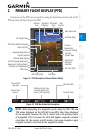
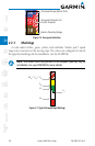
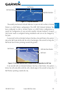
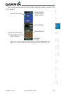
Roll Pointer
Slip/Skid Indicator
Roll Scale Zero
Figure 2-11 Slip/Skid Indication
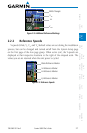
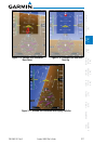
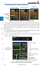
The standby mechanical Attitude Indicator in your aircraft is either a Ground
Pointer or a Roll Pointer configuration. The GDU 620 Attitude Indicator has
been configured in either a Ground Pointer or a Roll Pointer configuration to
match the configuration of your aircraft’s standby Attitude Indicator. Ground/
Sky Pointer mode is configured during installation and can not be changed by
the pilot.
In an aircraft with an Attitude Indicator that has a Ground Pointer, the pointer
above the Roll Scale shifts with the roll or bank angle of the aircraft to keep the
Roll Scale Zero Pointer pointing towards the ground.
Roll Pointer
Roll Scale Zero Pointer
Roll Scale
Figure 2-12 Attitude Indicator with a Ground Pointer configuration in a left turn
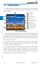
In an aircraft with an Attitude Indicator that has a Sky Pointer, the pointer
below the roll scale shifts with the roll or bank angle of the aircraft to keep the
Roll Pointer pointing towards the sky.