


4-94
Garmin G600 Pilot’s Guide
190-00601-02 Rev. E
Foreword
Sec 1
System
Sec 2
PFD
Sec 3
MFD
Sec 4
Hazard
Avoidance
Sec 5
Additional
Features
Sec 6
Annun.
& Alerts
Sec 7
Symbols
Sec 8
GlossaryAppendix A
Appendix B
Index
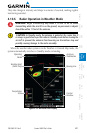
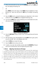
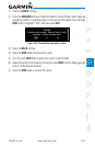
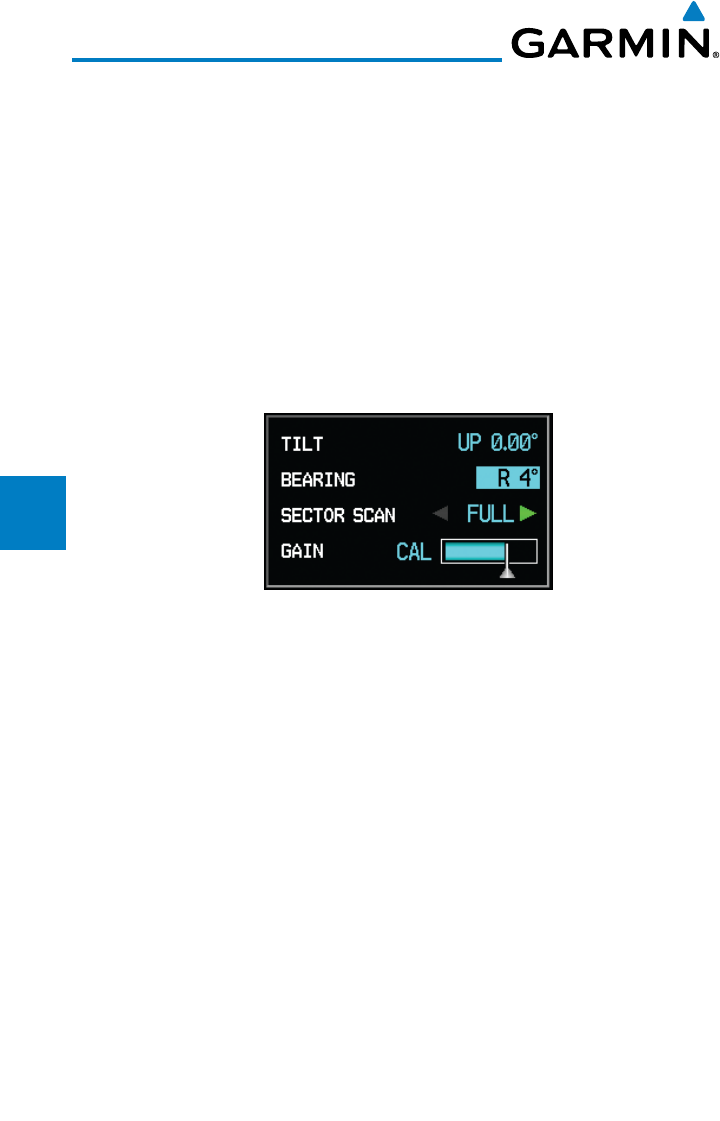
1) While in the Horizontal Scan view, press the CONTROL and then the BRG soft
keys. This displays the Bearing Line.
OR
Press MENU and turn the large or small MFD knobs to highlight the “Show
Bearing Line” menu item and press the ENT key. This displays the Bearing
Line.
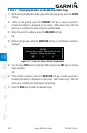
2) Press the MFD knob to activate the Bearing Line Adjustment in the Control
window. Turn the Large MFD knob to highlight the Bearing value.
3) Turn the small
MFD knob to place the Bearing Line on the desired storm cell or
other area to be vertically scanned.
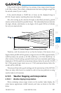
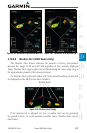
Figure 4-79 Bearing Line Adjustment
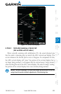
4) Press the
VERTICAL soft key. A vertical “slice” of the selected area will now be
displayed.
5) With the Bearing value still highlighted, the small
MFD Knob may be used to
move the scanned “slice” a few degrees right or left.
6) Press the RNG keys to adjust the range.
7) Press the MFD Knob to remove the cursor.
8) To select a new area to be vertically scanned, select the HORIZON soft key to
return to the Horizontal Scan view and repeat the previous steps.
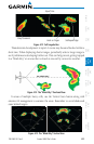
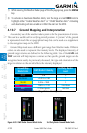
4.10.6.3 Adjusting the Antenna Tilt Angle
In order to make an accurate interpretation of a storm cell, the radar beam
should be pointed at the wet part of the weather cell to record the proper rainfall
intensity (color level). The ideal aiming point is just below the freezing level of
the storm. The best way to find this point is to use the Vertical Scan feature. The
antenna tilt angle can be centered on the strongest return area in the vertical
scan to get a more accurate view of the coverage and intensity of the target in
the horizontal scan.