


November 2003 © TOSHIBA TEC 3 - 17 e-STUDIO3511/4511 ADJUSTMENT
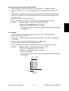
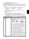
(e) Image location of secondary scanning direction
1. While pressing [0] and [5] simultaneously, turn the power ON. → (Adjustment Mode)
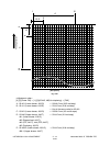
2. Place Test Chart No. TCC-1 on the original glass (with the arrow positioned at the left rear
side).
3. Press [FAX] → [START] to make a copy at the mode of A4/LT, 100%, Black and Text/Photo.
4. Measure the distance D from the top paper edge to the 10 mm line of top grid pattern on the
copy with a ruler.
5. Check if the distance D is within 10±0.5 mm.
6. If not, use the following procedure to change values and repeat step 3. to 5. above.
<Procedure> (Adjustment Mode) → (Key in the code [305]) → [START]
→ (Key in a value (acceptable values : 92 to 164))
→ [ENTER] or [INTERRUPT] (Stored in memory)
* The larger the adjustment value is, the longer the distance D becomes (approx.
0.14 mm/step).
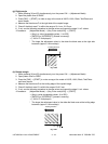
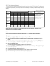
(f) Top margin
1. While pressing [0] and [5] simultaneously, turn the power ON. → (Adjustment Mode)
2. Open the platen cover or RADF.
3. Press [FAX] → [START] to make a copy at the mode of A3/LD, 100%, Black, Text/Photo and
lower drawer.
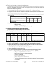
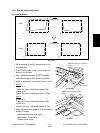
4. Measure the blank area E at the leading edge of the copied image.
5. Check if the blank area E is within the range of 3±0.5 mm.
6. If not, use the following procedure to change values and repeat the steps 3. to 5. above.
<Procedure> (Adjustment Mode) → (Key in the code [430]) → [START]
→ (Key in a value (acceptable values : 0 to 255))
→ [ENTER] or [INTERRUPT] (Stored in memory)
→ (“100% A” is displayed.)
* The larger the adjustment value is, the wider the blank area becomes (approx.
0.04 mm/step).
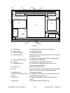
E
Feeding direction
Fig. 3-405