


November 2003 © TOSHIBA TEC 2 - 35 e-STUDIO3511/4511
ERROR CODE AND SELF-DIAGNOSTIC MODE
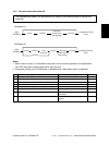
Initialization of
color auto-toner
sensor light
amount correction
target value
Initialization of color auto-
toner sensor light amount
correction target value
Enforced correction of color
auto-toner sensor light
amount
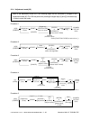
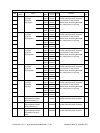
1st transfer roller bias output
adjustment
(When not transferred)
1st transfer roller
bias output
adjustment
(Image quality
control test
pattern)
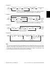
1st transfer roller
bias output
adjustment
200
201
202
203
204
206
207
208
210
211-0
211-1
211-2
211-3
212
214
215
216
217
Devel-
opment
Devel-
opment
Devel-
opment
Transfer
Transfer
Transfer
All
(Y,M,C,K)
Y
M
C
K
YMC
Y
M
C
K
Plain
paper
Thick
paper 1
Thick
paper 2
Thick
paper 3
OHP film
ALL
ALL
ALL
ALL
ALL
ALL
ALL
(color)
ALL
(color)
ALL
ALL
(color)
ALL
(color)
ALL
(color)
ALL
(color)
ALL
(black)
ALL
(black)
ALL
(black)
ALL
(black)
ALL
(black)
-
<0-255>
-
<0-255>
-
<0-255>
-
<0-255>
-
<0-255>
-
<0-255>
-
-
225
<0-225>
140
<0-225>
140
<0-225>
140
<0-225>
148
<0-225>
135
<0-225>
135
<0-225>
135
<0-225>
135
<0-225>
135
<0-225>
M
M
M
M
M
M
M
M
M
M
M
M
M
M
M
M
M
M
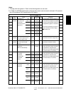
The value starts changing approx. 3
minutes after this adjustment started.
The value is automatically set during
this adjustment (approx. 2 minutes).
(As the value increases, the sensor
output increases correspondingly.)
(
Chapter 3.2)
Initializes the color auto-toner sensor
light amount correction target value.
Performs the color auto-toner sensor
light amount correction forcibly.
When the value decreases, the 1st
transfer roller bias output increases.
The adjustment value becomes
effective when the Setting Mode (08-
541, 549 and 551) is 0 (invalid).
When the value decreases, the 1st
transfer roller bias output increases.
The adjustment value becomes
effective when the Setting Mode (08-
541, 549 and 551) is 0 (invalid).
When the value decreases, the 1st
transfer roller bias output increases.
The adjustment value becomes
effective when the Setting Mode (08-
541, 549 and 551) is 0 (invalid).
5
5
5
5
5
5
6
6
3
14
14
14
14
3
3
3
3
3
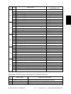
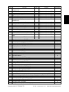
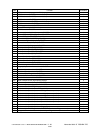
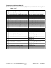
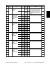
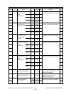
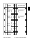
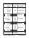
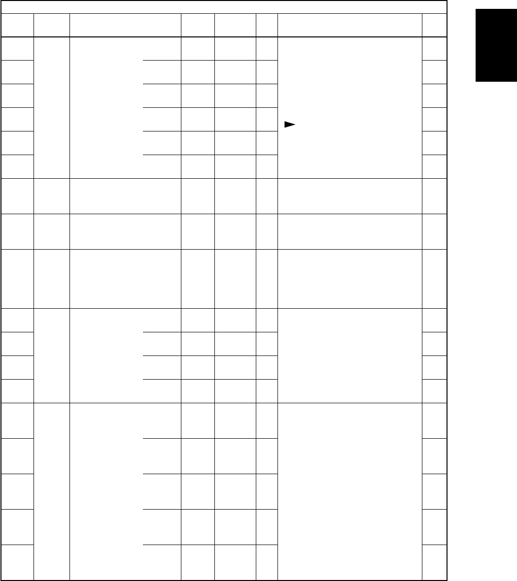
Adjustment mode (05)
Code
Classifi-
cation
Items
Func-
tion
Default
<Acceptable
value>
RAM Contents
Proce-
dure
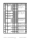
Notes:
1.The digit after the hyphen in “Code” of the following table is a sub code.
2.In “RAM”, the NVRAM of the board in which the data of each code is stored is indicated. “M” stands for
the LGC board and “SYS” stands for the SYS board.
04/05