


November 2003 © TOSHIBA TEC 2 - 43 e-STUDIO3511/4511
ERROR CODE AND SELF-DIAGNOSTIC MODE
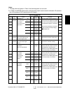
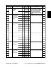
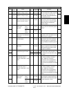
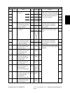
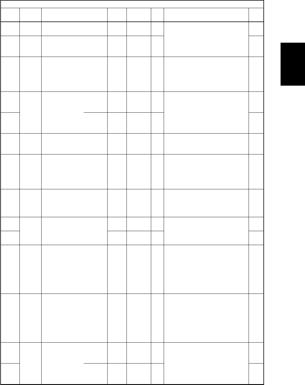
Color developer bias DC (-)
calibration voltage 1 (low)
Color developer bias DC (-)
calibration voltage 2 (high)
Reproduction ratio adjust-
ment of secondary scanning
direction (scanner section)
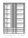
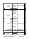
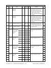
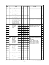
Adjustment of
RADF paper
alignment
Automatic adjustment of
RADF sensor and EEPROM
initialization
Fine adjustment of RADF
transport speed
RADF sideways deviation
adjustment
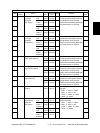
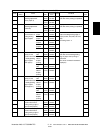
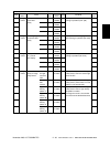
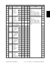
Carriage position adjustment
during scanning from RADF
Data transfer of
characteristic value of
scanner / SYS board -> SLG
board
Data transfer of
characteristic value of
scanner / SLG board -> SYS
board
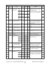
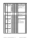
RADF leading
edge position
adjustment
338
339
340
354
355
356
357
358
359
360
363
364
365
366
Image
control
Image
control
Scanner
RADF
RADF
RADF
RADF
Scanner
Scanner
Scanner
RADF
for single-
sided
original
for double
sided
original
for single-
sided
original
for double
sided
original
ALL
ALL
ALL
ALL
ALL
ALL
ALL
ALL
ALL
(black)
ALL
(color)
SCN
SCN
ALL
ALL
100
<85-115>
900
<810-990>
127
<0-255>
10
<0-20>
10
<0-20>
-
50
<0-100>
128
<0-255>
128
<0-255>
128
<0-255>
-
-
50
<0-100>
50
<0-100>
M
M
SYS
SYS
SYS
SYS
SYS
SYS
SYS
SYS
SYS
SYS
SYS
SYS
Transformer output calibration of the
color developer bias. When replacing
the high-voltage transformer, the
values listed in attached data sheet
are entered. (Unit: V)
When the value increases by “1”, the
reproduction ratio in the secondary
scanning direction (vertical to paper
feeding direction) increases by
approx. 0.223%.
When the value increases by “1”, the
aligning amount increases by approx.
0.5mm.
Performs the adjustment and
initialization when the RADF board or
RADF sensor is replaced.
When the value increases by “1”, the
reproduction ratio of the secondary
scanning direction on original (fed
from the RADF) increases by approx.
0.1%.
When the value increases by “1”, the
image of original fed from the RADF
shifts toward the rear side of paper
by approx. 0.0423mm.
When the value increases by “1”, the
carriage position shifts by approx. 0.1
mm toward the exit side when using
the RADF.
Transfers the characteristic values of
the scanner (shading correction
factor / RGB color correction /
reproduction ratio color aberration
correction) from the NVRAM of the
SYS board to the NVRAM of the SLG
board.
Transfers the characteristic values of
the scanner (shading correction
factor / RGB color correction /
reproduction ratio color aberration
correction) from the NVRAM of the
SLG board to the NVRAM of the SYS
board.
When the value increases by “1”, the
copied image of original fed from the
RADF shifts toward the trailing edge
of paper by approx. 0.1mm.
1
1
1
1
1
6
1
1
1
1
6
6
1
1
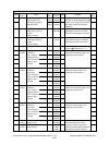
Adjustment mode (05)
Code
Classifi-
cation
Items
Func-
tion
Default
<Acceptable
value>
RAM Contents
Proce-
dure
04/10