


November 2003 © TOSHIBA TEC 3 - 61 e-STUDIO3511/4511 ADJUSTMENT
3.12.3 Adjustment of skew
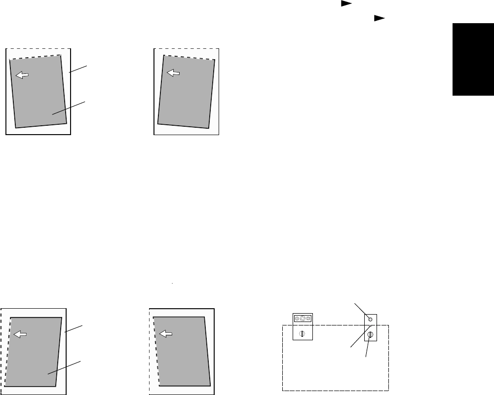
When an image skew occurs, adjust it according to the following steps, Step 1 → Step 2 → Step 3.
Note:
Perform this adjustment after confirming that the equipment has been adjusted properly.
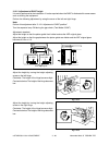
Prior to this adjustment, of RADF position and height are needed to be adjusted.
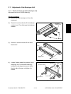
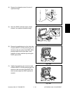
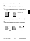
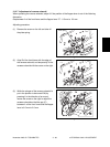
Step 1
Case A: Adjust the aligning adjustment position to the rear side “-” of the original ( Chapter 3.12.5).
Case B: Adjust the aligning adjustment position to the rear side “+” of the original ( Chapter
3.12.5).
White arrow: feeding direction
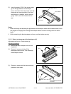
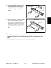
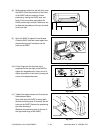
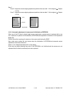
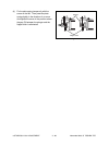
Step 2
Case C: Loosen the fixing screw and hand screw of the right side hinge and then turn the adjustment
screw counterclockwise.
Case D: Loosen the fixing screw and hand screw of the right side hinge and then turn the adjustment
screw clockwise.
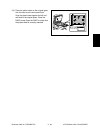
Note:
When adjusting, refer to the hinge position (scribed line) and be sure not to move it from the hinge
position ±0.5 mm or further. Otherwise, image failures such as a jitter may occur.
Paper
Original
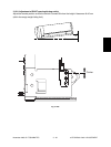
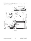
Fixing screw
Adjustment screw
Hand screw
Front side
Paper
Original
Fig. 3-1216
Fig. 3-1217
Fig. 3-1218
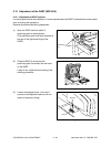
RADF
04/05