


e-STUDIO3511/4511
ERROR CODE AND SELF-DIAGNOSTIC MODE
2 - 42 November 2003 © TOSHIBA TEC
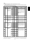
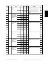
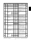
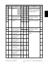
Displays the value of 2nd transfer
roller bias on the leading/trailing edge
of paper when printing is performed.
(The value corrected in 05-293 is
displayed.)
When the value increases by “1”, the
image shifts by approx. 0.137mm
toward the trailing edge of the paper.
When the value increases by “1”, the
image shifts by approx. 0.0423mm
toward the front side of the paper.
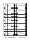
Moves carriages to the adjusting
position. ( Chapter 3. 4. 4.)
Sets the maximum correction number
of time of the contrast voltage in the
closed-loop control mode 2.
Sets the maximum correction number
of time of the laser power in the
closed-loop control mode 2.
Sets the maximum correction number
of time of the contrast voltage in the
closed-loop control mode 1.
Sets the maximum correction number
of time of the laser power in the
closed-loop control mode 1.
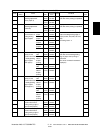
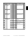
Transformer output calibration of the
main charger grid bias. When
replacing the high-voltage trans-
former, the values listed in attached
data sheet are entered. (Unit: V)
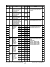
M
M
SYS
SYS
-
M
M
M
M
M
M
M
M
M
M
M
M
M
M
M
M
M
M
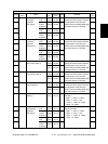
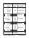
121
<0-255>
116
<0-255>
124
<92-164>
113
<0-255>
-
3
<0-255>
3
<0-255>
3
<0-255>
3
<0-255>
2
<0-255>
2
<0-255>
2
<0-255>
2
<0-255>
1
<0-255>
1
<0-255>
1
<0-255>
1
<0-255>
1
<0-255>
1
<0-255>
1
<0-255>
1
<0-255>
300
<270-330>
1200
<1080-
1320>
10
10
1
1
6
4
4
4
4
4
4
4
4
4
4
4
4
4
4
4
4
1
1
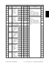
299-0
299-1
305
306
308
330-0
330-1
330-2
330-3
331-0
331-1
331-2
331-3
332-0
332-1
332-2
332-3
333-0
333-1
333-2
333-3
334
335
Transfer
Scanner
Scanner
Scanner
Image
control
Image
control
Image
control
Image
control
Image
control
Image
control
Actual value display of 2nd
transfer roller bias of
leading/trailing edge of
paper (OHP film)
Image location adjustment
of secondary scanning
direction
(scanner section)
Image location adjustment
of secondary scanning
direction
(scanner section)
Distortion mode
Image quality
closed-loop
control contrast
voltage correction/
Mode 2 maximum
number of time
corrected
Image quality
closed-loop
control laser
power correction/
Mode 2 maximum
number of time
corrected
Image quality
closed-loop
control contrast
voltage correction/
Mode 1 maximum
number of time
corrected
Image quality
closed-loop
control laser
power correction/
Mode 1 maximum
number of time
corrected
Main charger grid calibration
voltage 1 (low)
Main charger grid calibration
voltage 2 (high)
ALL
(black)
ALL
(color)
ALL
ALL
ALL
ALL
ALL
ALL
ALL
ALL
ALL
ALL
ALL
ALL
ALL
ALL
ALL
ALL
ALL
ALL
ALL
ALL
ALL
Y
M
C
K
Y
M
C
K
Y
M
C
K
Y
M
C
K
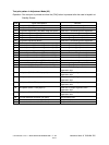
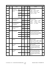
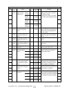
Adjustment mode (05)
Code
Classifi-
cation
Items
Func-
tion
Default
<Acceptable
value>
RAM Contents
Proce-
dure
04/09