


e-STUDIO3511/4511 ADJUSTMENT 3 - 58 November 2003 © TOSHIBA TEC
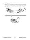
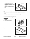
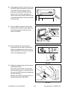
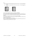
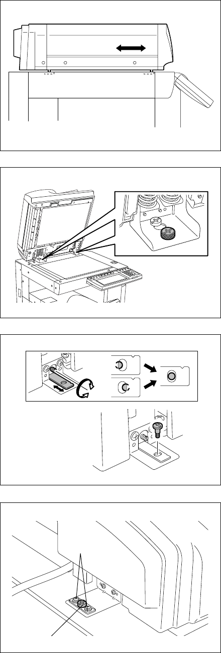
(8) While peering inside from the left side, close
the RADF. Check the positions of the holes
of the RADF and pins and then fit their
positions by moving the RADF back and
forth. (For the front side, also adjust the
RADF position right and left.) Make sure not
to dislocate the positions of the pin and hole
at the rear side.
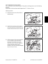
(9) Open the RADF to tighten 2 hand screws.
Close the RADF and then check again that
the positioning pins fit smoothly into the
holes on the RADF.
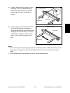
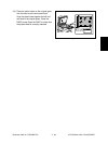
(11) Tighten the stepped screw and 2 screws on
the adjustment plate.
Open and close the RADF to check again
that the positioning pins fit smoothly into the
holes on the RADF. Remove the positioning
pins after checking it.
(Replace the positioning pins at the rear of
the right-hand hinge of the RADF.)
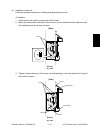
(10) Fit the hinge hole into the hole of the
equipment at the rear right of the RADF to
tighten the stepped screw. If they do not fit,
adjust the position of the hole by turning the
screw of the adjustment plate.
Screw
Stepped Screw
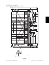
Fig. 3-1208
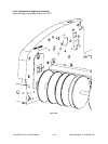
Fig. 3-1209
Fig. 3-1210
Fig. 3-1211