


November 2003 © TOSHIBA TEC 2 - 45 e-STUDIO3511/4511
ERROR CODE AND SELF-DIAGNOSTIC MODE
408
<0-999>
408
<0-999>
408
<0-999>
408
<0-999>
78
<0-255>
84
<0-255>
87
<0-255>
94
<0-255>
135
<0-255>
137
<0-255>
139
<0-255>
146
<0-255>
0
<0-1023>
0
<0-1023>
0
<0-1023>
0
<0-1023>
0
<0-1023>
0
<0-1023>
M
M
M
M
M
M
M
M
M
M
M
M
M
M
M
M
M
M
384-0
384-1
384-2
384-3
385-0
385-1
385-2
385-3
386-0
386-1
386-2
386-3
388
389
390-0
390-1
390-2
390-3
Image
control
Image
control
Image
control
Image
control
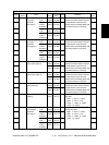
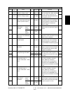
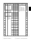
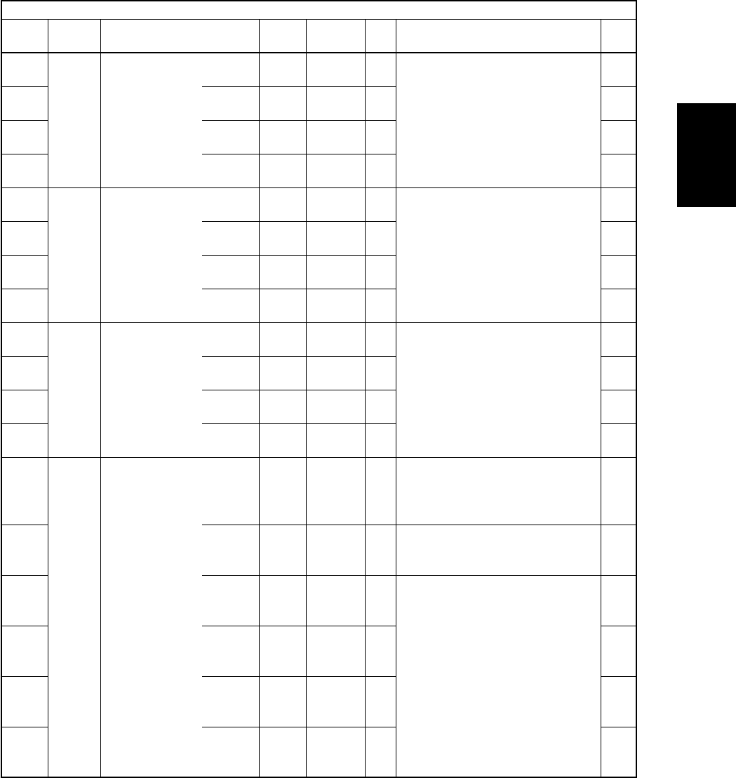
Laser power
actual value
display
Main charger grid
bias actual value
display
Developer bias
DC (-) actual
value display
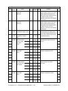
Output value
display of image
quality sensor
ALL
ALL
ALL
ALL
ALL
ALL
ALL
ALL
ALL
ALL
ALL
ALL
ALL
ALL
ALL
ALL
ALL
ALL
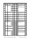
Displays the laser power when
printing is operated. (Unit: µW)
Displays the main charger grid bias
when printing is operated. (bit value)
Displays the developer bias when
printing is operated. (bit value)
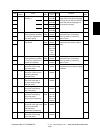
Displays the output value of image
quality sensor when the sensor light
source is OFF.
Displays the output value of image
quality sensor (when there is no test
pattern) on the transfer belt.
Displays the output value of image
quality sensor when a high-density
test pattern is written.
The larger the value is, the smaller
the toner amount adhered becomes.
10
10
10
10
10
10
10
10
10
10
10
10
2
2
10
10
10
10
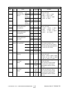
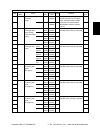
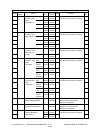
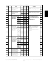
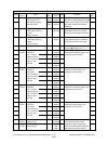
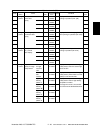
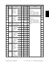
Adjustment mode (05)
Code
Classifi-
cation
Items
Func-
tion
Default
<Acceptable
value>
RAM Contents
Proce-
dure
Y
M
C
K
Y
M
C
K
Y
M
C
K
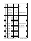
When
the light
source is
OFF
Transfer
belt
surface
High-
density
pattern Y
High-
density
pattern M
High-
density
pattern C
High-
density
pattern K