


November 2003 © TOSHIBA TEC 5 - 61 e-STUDIO3511/4511 TROUBLESHOOTING
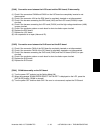
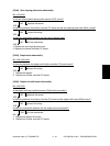
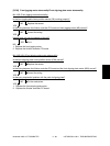
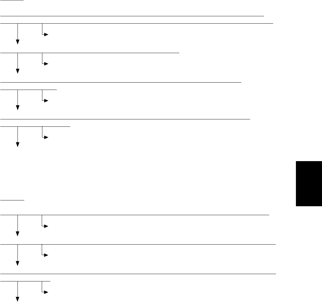
[CC10] Microswitch abnormality
MJ-1024
Are the front cover switch (MS31), inlet door switch (SW1) and delivery door switch (SW3) normal?
NO Replace the switches.
YES
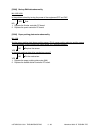
Measure the voltage between J704-1 (+) and J704-2 (-) on the finisher controller PC board. Is it 24V?
NO Replace the finisher controller PC board.
YES
Is the wiring between J704 on the finisher controller PC board and J1 on the saddle stitcher controller
PC board correct?
NO Correct the wiring.
YES
Replace the saddle stitcher controller PC board.
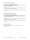
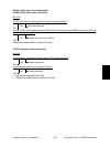
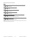
[CC00] Sensor connector abnormality
MJ-1024
Are the guide home position sensor (PI13), paper pushing plate home position sensor (PI14) and
paper pushing plate top position sensor (PI15) connected to the saddle stitcher controller PC board?
NO Connect them to the board.
YES
Is the wiring between the sensors and the saddle stitcher correct?
NO Correct the wiring.
YES
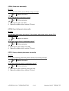
Is 5V DC being supplied from the connector pins J9-7, -10 and -13 on the saddle stitcher
controller PC board?
NO Replace the saddle stitcher controller PC board.
YES
Are the connector pins J9-8, -11 and -14 on the saddle stitcher controller PC board correctly
connected to the ground?
NO Replace the saddle stitcher controller PC board.
YES
End.