


119
Parameter List
Parameter List
4
DRIVING THE MOTOR
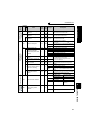
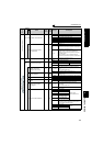
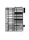
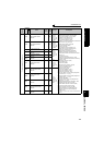
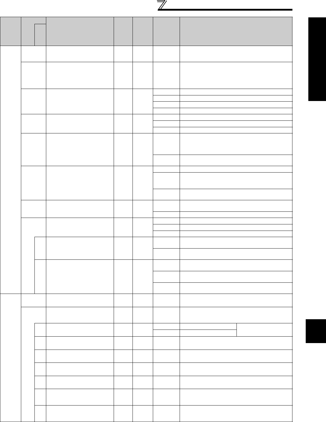
PU connector communication
117
PU communication station
number
100 to 31
Specify the inverter station number.
Set the inverter station numbers when two or more
inverters are connected to one personal computer.
118
PU communication speed
1 192
48, 96, 192,
384
Set the communication speed.
The setting value ×
100 equals the communication
speed.
For example, the communication speed is 19200bps
when the setting value is "192".
119
PU communication stop bit
length
11
0 Stop bit length: 1bit data length: 8bit
1 Stop bit length: 2bit data length: 8bit
10 Stop bit length: 1bit data length: 7bit
11 Stop bit length: 2bit data length: 7bit
120
PU communication parity
check
12
0 Without parity check
1 With odd parity check
2 With even parity check
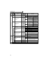
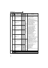
121
Number of PU
communication retries
11
0 to 10
Set the permissible number of retries at occurrence
of a data receive error.
If the number of consecutive errors exceeds the
permissible value, the inverter trips.
9999
If a communication error occurs, the inverter will not
come to trip.
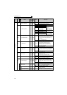
122
PU communication check
time interval
0.1s 9999
0 No PU connector communication
0.1 to 999.8s
Set the communication check time interval.
If a no-communication state persists for longer than
the permissible time, the inverter trips.
9999
No communication check
(signal loss detection)
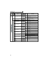
123
PU communication waiting
time setting
1 9999
0 to 150ms
Set the waiting time between data transmission to the
inverter and response.
9999 Set with communication data.
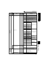
124
PU communication CR/LF
selection
11
0 Without CR/LF
1 With CR
2 With CR/LF
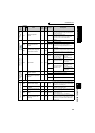
342
Communication EEPROM
write selection
10
0
Parameter values written by communication are written
to the EEPROM and RAM.
1
Parameter values written by communication are
written to the RAM.
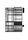
551
PU mode operation
command source selection
12
1
Select the RS-485 terminals as PU operation mode
control source.
2
Select the PU connector as PU operation mode
control source.
3
Select the USB connector as PU operation mode
control source.
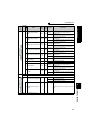
Change of analog input frequency,
adjustment of voltage, current input and frequency
(calibration)
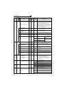
125
Terminal 2 frequency setting
gain frequency
0.01Hz 60Hz 0 to 400Hz
Set the frequency of terminal 2 input gain
(maximum).
126
Terminal 4 frequency setting
gain frequency
0.01Hz 60Hz 0 to 400Hz
Set the frequency of terminal 4 input gain
(maximum).
(Valid when Pr. 858 = 0 (initial value))
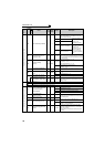
241
Analog input display unit
switchover
10
0 Displayed in %
Select the unit for analog
input display.
1 Displayed in V/mA
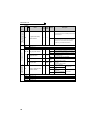
C2
(902)
Terminal 2 frequency setting
bias frequency
0.01Hz 0Hz 0 to 400Hz Set the frequency on the bias side of terminal 2 input.
C3
(902)
Terminal 2 frequency setting
bias
0.1% 0% 0 to 300%
Set the converted % of the bias side voltage (current)
of terminal 2 input.
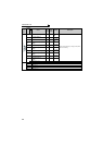
C4
(903)
Terminal 2 frequency setting
gain
0.1% 100% 0 to 300%
Set the converted % of the gain side voltage of
terminal 2 input.
C5
(904)
Terminal 4 frequency setting
bias frequency
0.01Hz 0Hz 0 to 400Hz
Set the frequency on the bias side of terminal 4 input.
(Valid when Pr. 858 = 0 (initial value))
C6
(904)
Terminal 4 frequency setting
bias
0.1% 20% 0 to 300%
Set the converted % of the bias side current (voltage)
of terminal 4 input.
(Valid when Pr. 858 = 0 (initial value))
C7
(905)
Terminal 4 frequency setting
gain
0.1% 100% 0 to 300%
Set the converted % of the gain side current (voltage)
of terminal 4 input.
(Valid when Pr. 858 = 0 (initial value))
The parameter number in parentheses is the one for use with the parameter unit (FR-PU04/FR-PU07).
Func
t
ion
Parameter
Name
Incre
ments
Initial
Value
Range Description
Related
parameters