


18
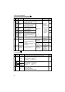
Main circuit terminal specifications
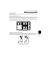
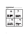
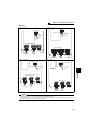
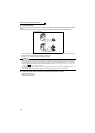
(3) Total wiring length
The overall wiring length for the connection to a single motor or multiple motors should be within 500m (with unshielded
wires).
(The wiring length should be within 100m for the operation under vector control or when using shielded wires.)
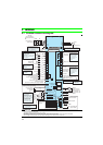
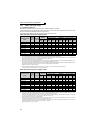
(4) Cable size of the control circuit power supply (terminal R1/L11, S1/L21)
· Terminal screw size: M4
· Cable size: 0.75mm
2
to 2mm
2
· Tightening torque: 1.5N·m
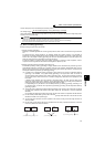
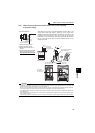
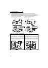
Total wiring length
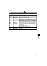
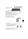
When driving a 400V class motor by the inverter, surge voltages attributable to the wiring constants may occur at
the motor terminals, deteriorating the insulation of the motor.
Refer to page 42 for measures against deteriorated insulation.
CAUTION
· Especially with the long-distance wiring and the wiring with shielded wires, the inverter may be affected by a charging current
caused by the stray capacitance from the wiring, leading to a malfunction of the overcurrent protective function or the fast response
current limit function, or an inverter fault. It may also lead to a malfunction or fault of the equipment connected on the inverter output
side. Stray capacitance from the wiring varies with its wiring conditions. The overall wiring length specified above is only a reference
value. If the fast-response current limit function malfunctions, disable this function. (For Pr. 156 Stall prevention operation selection, refer
to Chapter 4 of the Instruction Manual (Applied).)
· For explanation of the surge voltage suppression filter (FR-ASF-H/FR-BMF-H) and sine wave filter (MT-BSL/BSC), refer to the
manual of each option.
· Do not connect a surge voltage suppression filter (FR-ASF-H/FR-BMF-H) during the operation under vector control.
500m or less
300m
300m
300m + 300m = 600m