


135
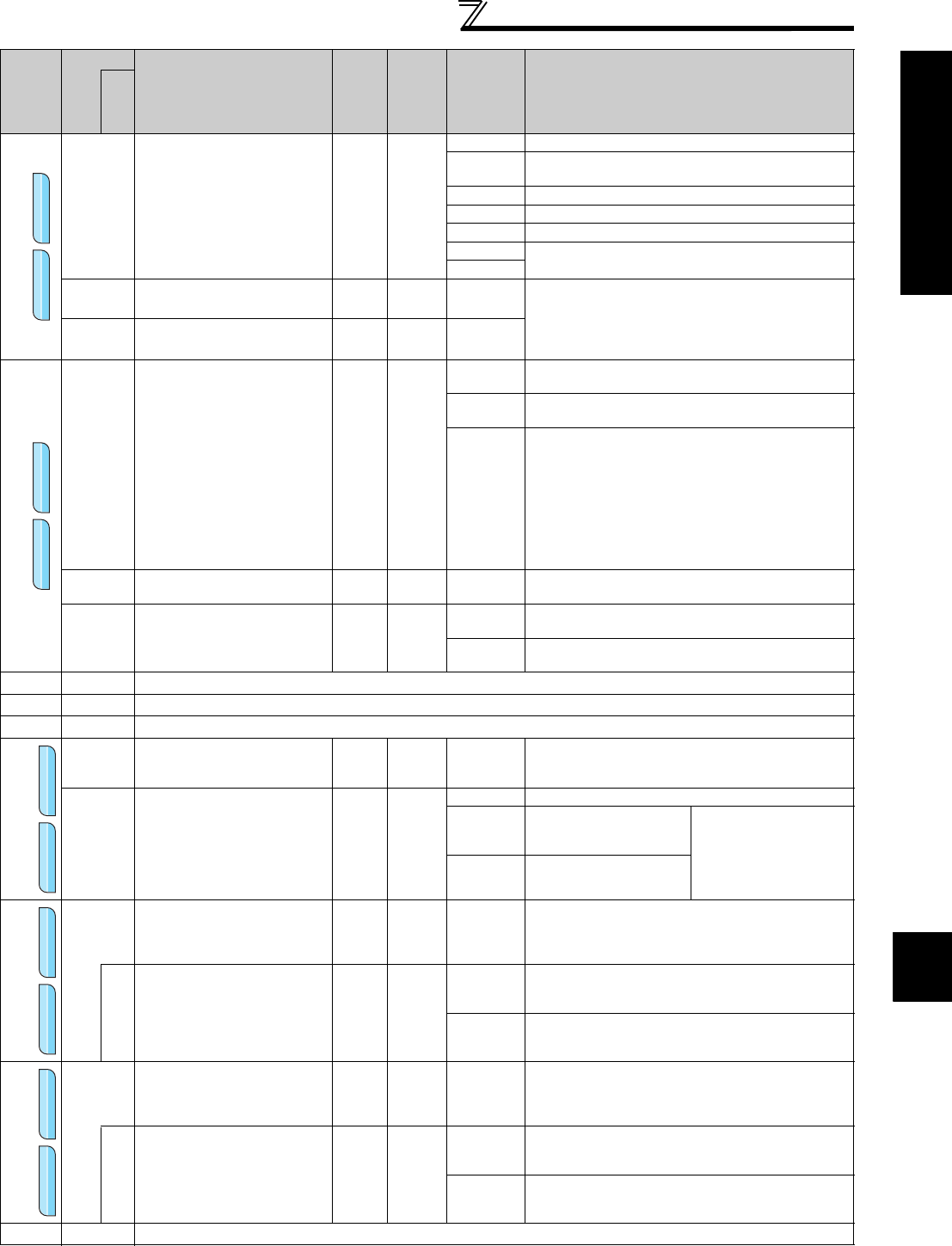
Parameter List
Parameter List
4
DRIVING THE MOTOR
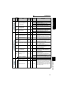
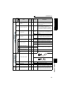
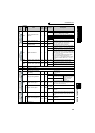
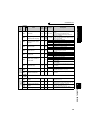
Torque command source selection
804
Torque command source
selection
10
0 Torque command by terminal 1 analog input
1
Torque command by parameter
Pr.805 or Pr.806 setting (-400% to 400%)
2 Torque command using pulse train input (FR-A7AL)
3 Torque command by using CC-Link (FR-A7NC)
4 Digital input from the option (FR-A7AX)
5
Torque command by using CC-Link (FR-A7NC)
6
805
Torque command value
(RAM)
1% 1000%
600 to
1400%
Digital setting of the torque command can be made
by setting Pr. 805 or Pr. 806. (Setting from
communication option, etc. can be made.)
In this case, set the speed limit value to an
appropriate value to prevent overspeed.
806
Torque command value
(RAM,EEPROM)
1% 1000%
600 to
1400%
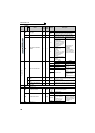
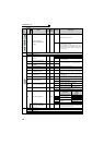
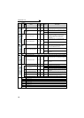
Speed limit
807
Speed limit selection
10
0
Use the speed command value during speed control
as speed limit.
1
According to Pr. 808 and Pr. 809, set the speed limit in
forward and reverse rotation directions individually.
2
The analog voltage of the terminal 1 input is used to
make speed limit. For 0 to 10V input, set the forward
rotation speed limit. (The reverse rotation speed limit
is Pr. 1 Maximum frequency)
For -10 to 0V input, set the reverse rotation speed
limit. (The forward rotation speed limit is Pr. 1
Maximum frequency.) The maximum frequency of both
the forward and reverse rotations is Pr. 1 Maximum
frequency.
808
Forward rotation speed limit
0.01Hz 60Hz 0 to 120Hz
Set the speed limit level during forward rotation.
(valid when Pr. 807 = 1)
809
Reverse rotation speed limit
0.01Hz 9999
0 to 120Hz
Set the speed limit level during reverse rotation.
(valid when Pr. 807 = 1)
9999
The setting is the same as that of the torque limit in
the forward rotation direction.
—
810
Refer to Pr. 22.
—
811
Refer to Pr. 22 and Pr. 37.
—
812 to 817
Refer to Pr. 22.
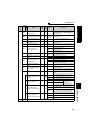
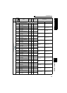
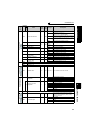
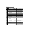
Easy gain
tuning selection
818
Easy gain tuning response
level setting
121 to 15
1 : Slow response
↓
15 : Fast response
819
Easy gain tuning selection
10
0 No tuning
1
With load estimation
(only under vector control)
The optimum gain is
automatically set from the
torque command and
speed during motor
operation.
2
Manual input of load (Pr.
880)
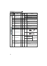
Speed loop proportional
gain setting
820
Speed control P gain 1
1% 60% 0 to 1000%
Set the proportional gain for speed control.
(Increasing the value improves trackability in
response to a speed command change and reduces
speed variation with disturbance.)
830
Speed control P gain 2
1% 9999
0 to 1000%
Second function of Pr. 820 (valid when RT signal is
on)
9999 No function
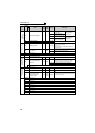
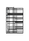
Speed control
integral time setting
821
Speed control integral time
1
0.001s 0.333s 0 to 20s
Set the integral time during speed control. (Decrease
the value to shorten the time taken for returning to
the original speed if speed variation with disturbance
occurs.)
831
Speed control integral time
2
0.001s 9999
0 to 20s
Second function of Pr. 821 (valid when the RT
terminal is on)
9999 No function
—
822
Refer to Pr. 74.
Func
t
ion
Parameter
Name
Incre
ments
Initial
Value
Range Description
Related
parameters
Sensorless
Sensorless
Sensorless Vector
Vector
VectorSensorless
Sensorless
Sensorless Vector
Vector
Vector
Sensorless
Sensorless
Sensorless Vector
Vector
VectorSensorless
Sensorless
Sensorless Vector
Vector
VectorSensorless
Sensorless
Sensorless Vector
Vector
Vector