


157
Causes and corrective actions
5
TROUBLESHOOTING
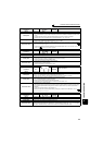
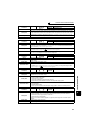
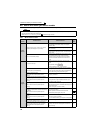
Operation Panel
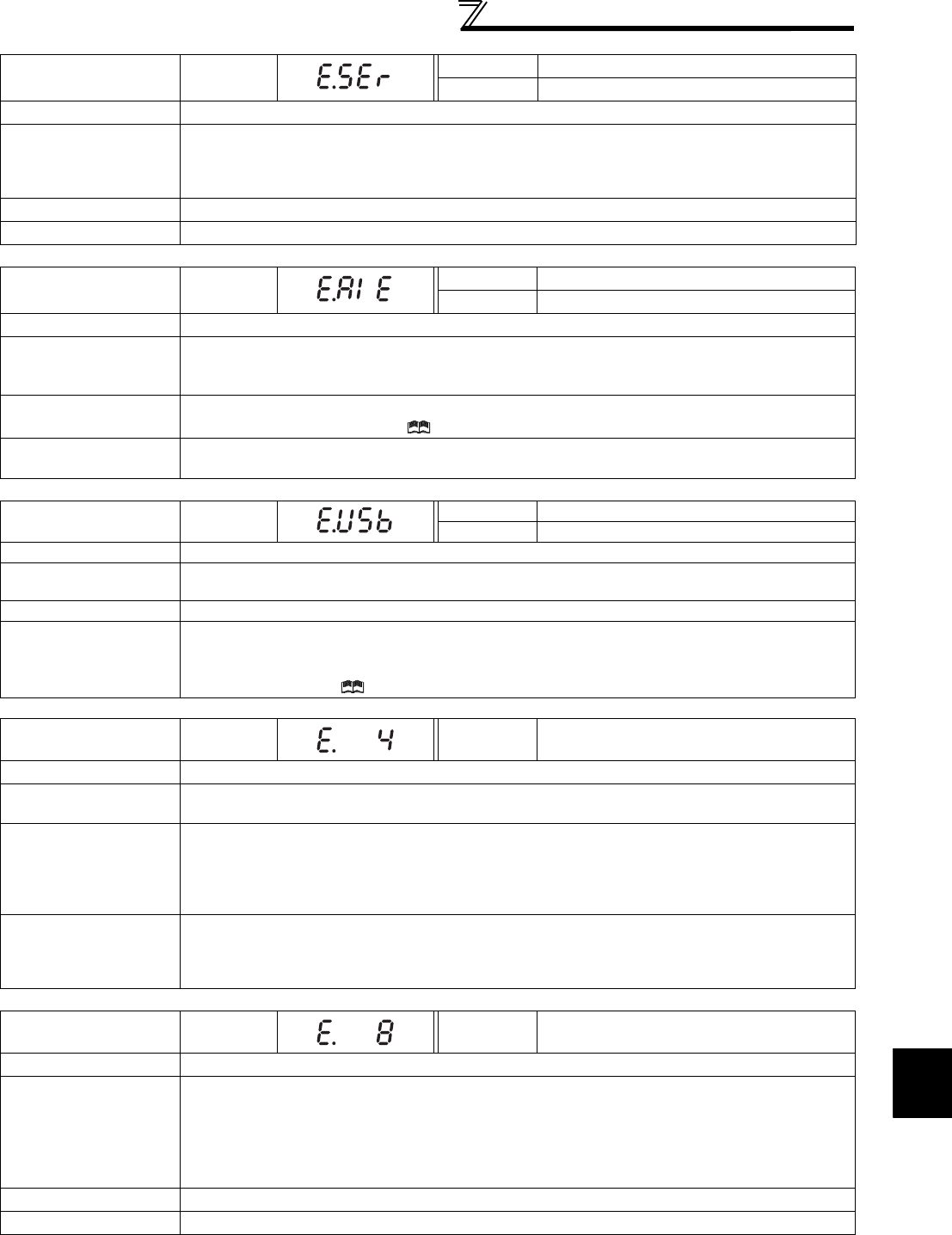
Indication
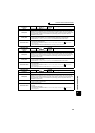
E.SER
FR-PU04 Fault 14
FR-PU07 VFD Comm error
Name
Communication fault (inverter)
Description
This function stops the inverter output when communication error occurs consecutively for more than
permissible retry count when a value other than "9999" is set in Pr. 335 RS-485 communication retry count
during RS-485 communication from the RS-485 terminals. This function also stops the inverter output if
communication is broken for the period of time set in Pr. 336 RS-485 communication check time interval.
Check point
Check the RS-485 terminal wiring.
Corrective action Perform wiring of the RS-485 terminals properly.
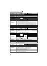
Operation Panel
Indication
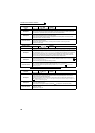
E.AIE
FR-PU04 Fault 14
FR-PU07 Analog in error
Name
Analog input fault
Description
Stops the inverter output when a 30mA or higher current or a 7.5V or higher voltage is input to terminal
2 while the current input is selected by Pr.73 Analog input selection, or to terminal 4 while the current
input is selected by Pr.267 Terminal 4 input selection.
Check point
Check the setting of Pr. 73 Analog input selection, Pr. 267 Terminal 4 input selection and voltage/current
input switch. (Refer to Chapter 4 of the Instruction Manual (Applied).)
Corrective action
Either give a frequency command by current input or set Pr. 73 Analog input selection, Pr. 267 Terminal 4
input selection, and voltage/current input switch to voltage input.
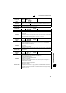
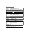
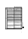
Operation Panel
Indication
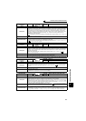
E.USB
FR-PU04 Fault 14
FR-PU07 USB comm error
Name
USB communication fault
Description
When the time set in Pr. 548 USB communication check time interval has broken, this function stops the
inverter output.
Check point
Check the USB communication cable.
Corrective action
y Check the Pr. 548 USB communication check time interval setting.
y Check the USB communication cable.
y Increase the Pr. 548 USB communication check time interval setting. Or, change the setting to 9999.
(Refer to Chapter 4 of the Instruction Manual (Applied))
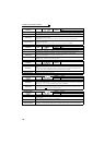
Operation Panel
Indication
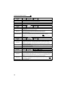
E.4
FR-PU04
FR-PU07
Fault 4
Name
Converter overcurrent
Description
The current flows in the regeneration converter module exceeds the specified value, protective circuit
activates and stops the inverter output.
Check point
y Check that sudden acceleration/deceleration is not performed.
y Check for sudden load change.
y Check that wiring is correct.
y Check that instantaneous power failure did not occur.
y Check that the thyristor load does not exist in the same power supply system.
Corrective action
y Increase acceleration/deceleration time.
y Keep load stable.
y Wire the cables properly.
y When a thyristor load exist in the same power supply system, install an AC reactor (FR-HAL).
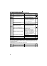
Operation Panel
Indication
E.8
FR-PU04
FR-PU07
Fault 8
Name
Power supply fault
Description
y When overvoltage occurs in the converter side during input phase failure detection
y When overvoltage occurs in the converter side during instantaneous power failure detection
y When fault of power supply frequency is detected
y When phase shift is not detected
When any of the above conditions applied, it is judged as power supply and the inverter output is
stopped.
Check point
Check the power supply and wiring.
Corrective action Perform wiring correctly.