


151
Causes and corrective actions
5
TROUBLESHOOTING
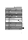
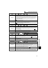
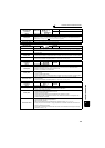
Operation Panel
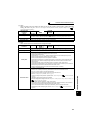
Indication
E.IPF
FR-PU04
FR-PU07
Inst. Pwr. Loss
Name
Instantaneous power failure
Description
If a power failure occurs for longer than 15ms (this also applies to inverter input shut-off), the
instantaneous power failure protective function is activated to trip the inverter in order to prevent the
control circuit from malfunctioning. If a power failure persists for longer than 100ms, the fault output is
not provided, and the inverter restarts if the start signal is on upon power restoration. (The inverter
continues operating if an instantaneous power failure is within 15ms.) In some operating status (load
magnitude, acceleration/deceleration time setting, etc.), overcurrent or other protection may be
activated upon power restoration.
When instantaneous power failure protection is activated, the IPF signal is output. (Refer to Chapter 4 of
the Instruction Manual (Applied))
Check point Find the cause of instantaneous power failure occurrence.
Corrective action
y Remedy the instantaneous power failure.
y Prepare a backup power supply for instantaneous power failure.
y Set the function of automatic restart after instantaneous power failure (Pr. 57). (Refer to Chapter 4 of
the Instruction Manual (Applied) .)
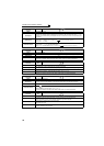
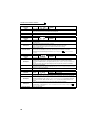
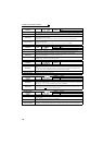
Operation Panel
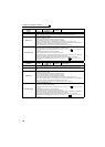
Indication
E.UVT
FR-PU04
FR-PU07
Under Voltage
Name
Undervoltage
Description
If the power supply voltage of the inverter decreases, the control circuit will not perform normal functions.
In addition, the motor torque will be insufficient and/or heat generation will increase. To prevent this, if
the power supply voltage decreases below about 150VAC (300VAC for the 400V class), this function
stops the inverter output.
When undervoltage protection is activated, the IPF signal is output. (Refer to Chapter 4 of the
Instruction Manual (Applied))
Check point
Check for start of large-capacity motor.
Corrective action
y Check the power supply system equipment such as the power supply.
y If the problem still persists after taking the above measure, please contact your sales representative.
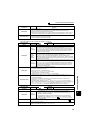
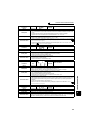
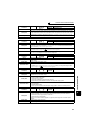
Operation Panel
Indication
E.ILF
FR-PU04 Fault 14
FR-PU07 Input phase loss
Name
Input phase loss
Description
This fault is output when function valid setting (= 1) is set in Pr. 872 Input phase loss protection selection
and one phase of the three phase power input is lost. (If the input power voltage is less than 100VAC,
the inverter may detect an input phase loss (E.ILF).) (Refer to Chapter 4 of the Instruction Manual
(Applied).)
Check point Check for a break in the cable for the three-phase power supply input.
Corrective action
y Wire the cables properly.
y Repair a break portion in the cable.
y Check the Pr. 872 Input phase loss protection selection setting.
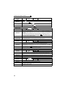
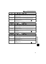
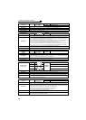
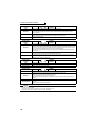
Operation Panel
Indication
E.OLT
FR-PU04
FR-PU07
Stll Prev STP ( OL shown during stall
prevention operation)
Name
Stall prevention stop
Description
If the frequency has fallen to 0.5Hz by stall prevention operation and remains for 3s, a fault (E.OLT)
appears and trips the inverter. OL appears while stall prevention is being activated.
When speed control is performed by Real sensorless vector control or vector control, a fault (E.OLT) is
displayed and the inverter output is stopped if frequency drops to the Pr. 865 Low speed detection (initial
value is 1.5Hz) setting by torque limit operation and the output torque exceeds Pr. 874 OLT level setting
(initial value is 150%) setting and remains for more than 3s.
Check point
y Check the motor for use under overload. (Refer to Chapter 4 of the Instruction Manual (Applied) .)
y Check that the Pr. 865 Low speed detection and Pr. 874 OLT level setting values are correct. (Check the
Pr. 22 Stall prevention operation level setting if V/F control is exercised.)
Corrective action
y Reduce the load weight.
y Change the Pr. 22 Stall prevention operation level, Pr. 865 Low speed detection and Pr. 874 OLT level
setting values. (Check the Pr. 22 Stall prevention operation level setting if V/F control is exercised.)