172
Inspection item
6.1.4 Display of the life of the inverter parts
The self-diagnostic alarm is output when the lifespan of the control circuit capacitor, cooling fan, each parts of the
inrush current limit circuit is near its end. It gives an indication of replacement time .
The life alarm output can be used as a guideline for life judgement.
For the life check of the main circuit capacitor, the alarm signal (Y90) will not be output if a measuring method of (2) is
not performed. (Refer to page 173.)
(1) Display of the life alarm
· Pr. 255 Life alarm status display can be used to confirm that the control circuit capacitor, main circuit capacitor,
cooling fan, and each parts of the inrush current limit circuit has reached the life alarm output level.
Parts Judgement Level
Main circuit capacitor 85% of the initial capacity
Control circuit capacitor Estimated 10% life remaining
Inrush current limit circuit Estimated 10% life remaining (Power on: 100,000 times left)
Cooling fan Less than 50% of the predetermined speed
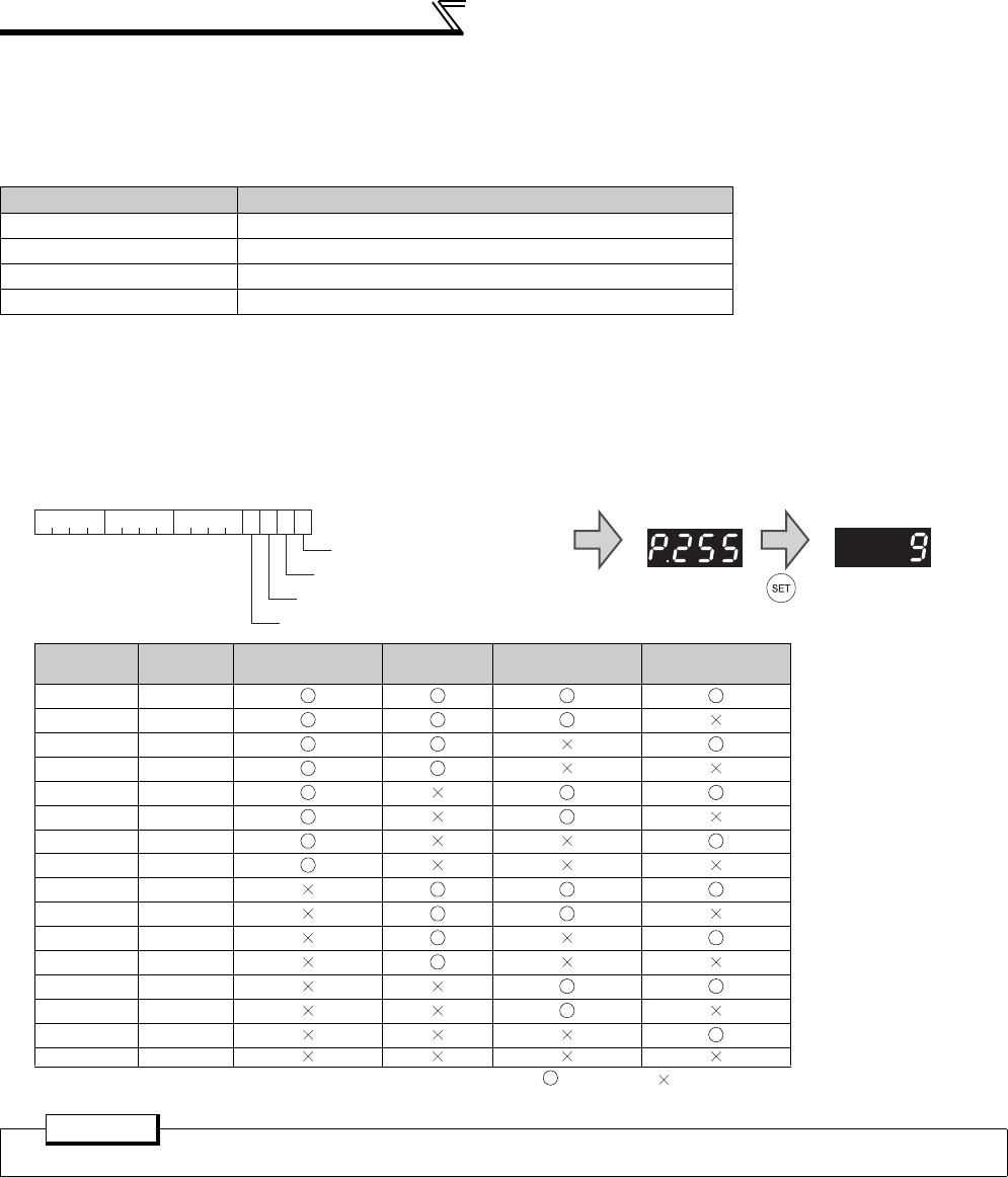
Pr. 255
(decimal)
Bit
(binary)
Inrush Current
Limit Circuit Life
Cooling
Fan
L
ife
Main
C
ircuit
C
apacitor
L
ife
Control
C
ircuit
C
apacitor
L
ife
15 1111
14 1110
13 1101
12 1100
11 1011
10 1010
9 1001
8 1000
7 0111
60110
5 0101
4 0100
30011
2 0010
1 0001
0 0000
: with alarm, : without alarm
POINT
Life check of the main circuit capacitor needs to be done by Pr. 259. (Refer to the following.)
0 0 0 0 0 0 0 0 0 0 0 0 1 0 0
bit0 Control circuit capacitor life
1
15bit 7 0
bit1 Main circuit capacitor life
bit2 Cooling fan life
bit3 Inrush current limit circuit life
• Pr.255 read
Bit image is displayed
in decimal
• Pr.255 setting read


