


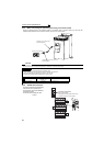
22
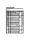
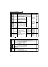
Control circuit specifications
*2 Refer to Chapter 4 of the Instruction Manual (Applied).
(3) Communication
Open collector
RUN
Inverter
running
Switched low when the inverter output frequency is equal to or
higher than the starting frequency (initial value 0.5Hz). Switched
high during stop or DC injection brake operation.
*1
Permissible load
24VDC (27VDC
maximum) 0.1A
(A voltage drop is
2.8V maximum
when the signal is
on.)
*1 Low is when the
open collector
output transistor is
ON (conducts).
High is when the
transistor is OFF
(does not
conduct).
*2
SU
Up to
frequency
Switched low when the output
frequency reaches within the range of
±10% (initial value) of the set frequency.
Switched high during acceleration/
deceleration and at a stop. *1
Alarm code (4bit)
output
*2
OL
Overload
warning
Switched low when stall prevention is
activated by the stall prevention
function. Switched high when stall
prevention is cancelled.
*1
*2
IPF
Instantaneous
power failure
Switched low when an instantaneous
power failure and under voltage
protections are activated.
*1
*2
FU
Frequency
detection
Switched low when the inverter output
frequency is equal to or higher than the
preset detected frequency and high
when less than the preset detected
frequency.
*1
*2
SE
Open collector
output common
C o m m o n t e r m i n a l f o r t e r m i n a l s R U N , S U , O L , I P F, F U -------------------- -----
Pulse
FM
For meter
Select one e.g. output frequency from
monitor items. Not output during
inverter reset.
The output signal is proportional to the
magnitude of the corresponding
monitoring item.
To set a full-scale value for monitoring
the output frequency and the output
current, set Pr. 56 and Pr.158.
*2
Output item:
Output frequency
(initial setting)
Permissible load
current 2mA
1440pulses/s at
60Hz
*2
NPN open
collector output
Signals can be output
from the open
collector terminals by
setting Pr. 291.
Maximum output
pulse: 50kpulses/s
Permissible load
current : 80mA
*2
Analog
AM
Analog signal
output
Output item:
Output frequency
(initial setting)
Output signal 0 to
10VDC
Permissible load
current 1mA
(load impedance
10kΩ or more)
Resolution 8 bit
*2
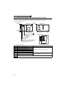
Type
Terminal
Symbol
Terminal
Name
Description
Refer to
page
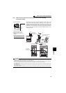
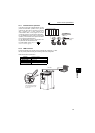
RS-485
--------------------
PU
connector
With the PU connector, communication can be made through RS-485.
(for connection on a 1:1 basis only)
. Conforming standard : EIA-485 (RS-485)
. Transmission format : Multidrop link
. Communication speed : 4800 to 38400bps
. Overall length : 500m
26
RS-485 terminals
TXD+
Inverter
transmission
terminal
With the RS-485 terminals, communication can be made through RS-485.
Conforming standard : EIA-485 (RS-485)
Transmission format : Multidrop link
Communication speed : 300 to 38400bps
Overall length : 500m
26
TXD-
RXD+
Inverter
reception
terminal
RXD-
SG
Earth (Ground)
USB
--------------------
USB
connector
The FR Configurator can be used by connecting the inverter to the personal
computer through USB.
Interface:Conforms to USB1.1
Transmission speed:12Mbps
Connector:USB B connector (B receptacle)
27
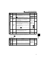
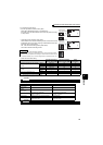
Type
Terminal
Symbol
Terminal
Name
Description
Rated
Specifications
Refer to
page